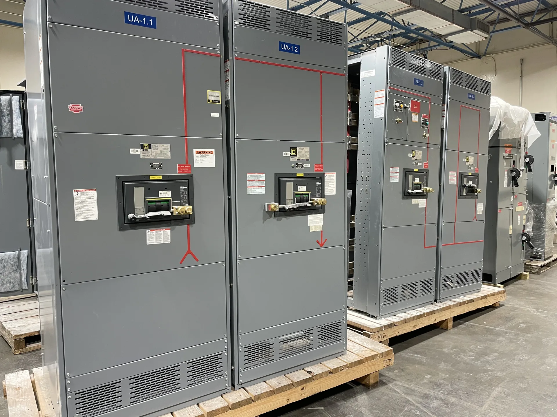
Compare single-high and two-high breaker arrangements for access, height, footprint, cable routing, and maintainability. A project-specific one-line, load information and physical constraints give the manufacturer a useful basis for discussion. We manufacture and supply new equipment in the United States for projects throughout North Carolina. Ratings and available options must be reviewed against the installation and the required documentation. Discuss your intended schedule and destination when requesting a quotation; lead time and shipping arrangements depend on the final scope.
Medium Voltage Switchgear Breaker Stacking — project planning
Metal-enclosed interrupter switchgear can be considered for medium-voltage distribution where the switching and protection scheme suits the connected loads. A feeder may use a load-interrupter switch and fuses, subject to the selected equipment's ratings and application. Define whether the duty is transformer protection, cable switching or another function, and provide normal load current, fault current and required isolation. Review fuse coordination, visible isolation provisions, interlocks and space for terminations. Metal-enclosed does not automatically mean metal-clad; compare the specified compartmentation and devices against the applicable standard and maintenance plan.
Metal-clad switchgear is a specific form of metal-enclosed medium-voltage switchgear, not simply any assembly with a metal exterior. IEEE C37.20.2 describes metal-clad construction with drawout electrically operated circuit breakers and grounded metal barriers separating key compartments. For a project, specify the required voltage class, bus current, fault ratings, relay functions and number of feeders. Consider breaker handling, compartment access, control power and maintenance procedures when evaluating the layout. Request confirmation of the applicable standard and the proposed design's construction and ratings; do not assume arc-resistant performance without documented evidence.
High-Voltage Project Scoping
High-voltage projects require a separate review of the utility interface, insulation coordination, switching duties and site constraints; a low-voltage switchboard specification is not a substitute. Begin with a one-line diagram, nominal and maximum system voltages, grounding method, expected load and utility-provided fault information. Identify required equipment boundaries, protective relays, communications, metering and ownership of the interconnection. The project team should establish applicable standards, clearances, studies and permitting responsibilities for the specific voltage and installation. Equipment configuration and scope should be confirmed through a project-specific technical review.
Switchgear layouts should give qualified personnel a practical way to inspect, test, isolate, and maintain equipment over its service life. Show required working space, door swing, cable access, and the route for removing major components on the project drawings. Identify isolation points and any alternate feeds or control-power sources that could leave parts energized. Procurement specifications can request durable labeling, accessible test provisions, and documentation of operating sequences. Maintenance plans should use site-specific procedures for controlling hazardous energy and verifying absence of voltage before work begins.
Busbar Work: Conductors and Support
Busbars distribute power within an assembly and must be designed as part of the complete electrical system. Conductor material, cross section, temperature rise, spacing, insulation, and support arrangement all affect suitability for the intended duty. The design must also account for mechanical forces associated with the specified short-circuit rating. Bending, punching, and routing should follow the approved construction details rather than rules of thumb alone. Phase identification and clear section interfaces help installers connect a lineup correctly while preserving required clearances and access.
A busbar joint depends on compatible materials, prepared contact surfaces, specified hardware, and the correct installation method. Surface treatment and joint compounds, when required, should follow the assembly and component instructions rather than a generic recipe. Fasteners should be tightened to the specified torque using suitable tools, with access provided for inspection and maintenance. The same care applies to field-installed splice connections between shipping sections. Unapproved drilling, substitution, or rework can affect current carrying capacity, clearances, or short-circuit performance and should be reviewed before proceeding.
Engineering Review: Checking the Complete Design
Engineering review compares the proposed equipment with the project's electrical and physical requirements before construction proceeds. The review can address single-line diagrams, device ratings, available fault current, grounding, control interfaces, enclosure selection, and installation constraints. Protective device settings and coordination depend on the broader power system and may require separate studies by the responsible design professional. Drawing revisions and equipment substitutions should be tracked so all parties work from the same information. Approval of a drawing alone does not replace required product evaluation, inspection, or authority approval.
Short-circuit current rating, or SCCR, describes the fault current an assembly or component can withstand under specified conditions at a stated voltage. A breaker's or fuse's interrupting rating describes the fault current that device can safely interrupt under specified conditions. Both must be considered against the available fault current at the installation point; a high breaker rating alone does not establish the assembly rating. A qualified designer should also review any conditions attached to the equipment rating. Series-rated combinations require specific permitted device combinations and application checks, not an assumption based on the upstream breaker alone.
Custom Design: Planning the Physical Layout
A project-specific equipment layout connects electrical requirements to the space available for installation and maintenance. Section dimensions, cable entry, conductor bending space, ventilation, and access to operating devices all influence the arrangement. The design should account for doors, removable covers, lifting provisions, and the working clearances required at the installed location. Coordination with the building team helps identify obstructions, floor loading, and the route into the electrical room. A documented layout also makes it easier to review future expansion without assuming unused space is automatically suitable for additional equipment.
Installation planning starts with the approved equipment dimensions, shipping splits, weights, and manufacturer's handling instructions. Check the route from the unloading point to the electrical room, including doors, elevators, floor loading, rigging access, and the final equipment pad or supports. Coordinate conduit locations, cable bending space, grounding, utility interfaces, and any required shutdown with the responsible trades. Define who will store, assemble, install, test, and commission the equipment. Arrange inspections and any required permits before energization. Early coordination can reveal access or sequencing problems while there is still time to address them.
Start with the right specifications
Final capabilities and ratings are confirmed against the application, approved drawings and quotation.
| Project detail | What to provide |
|---|---|
| System | Voltage, phase, wiring and grounding |
| Current | Main and feeder ratings; load information |
| Protection | Available fault current, SCCR and protective device requirements |
| Installation | Enclosure, space, utility requirements and destination |