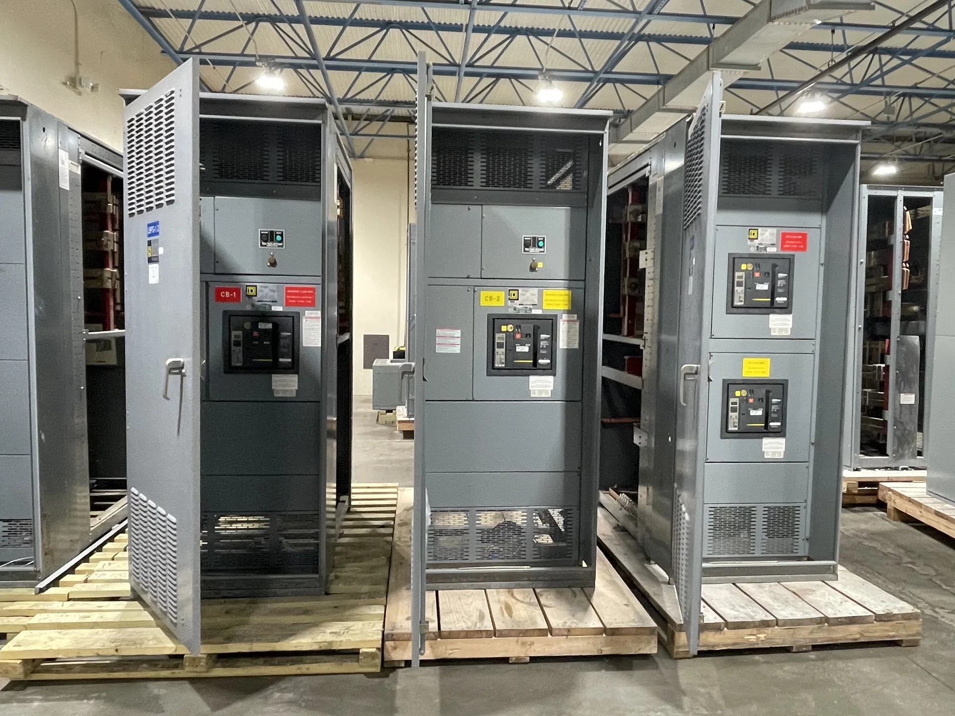
Assess compatibility, existing compartment condition, trip functionality, testing, and documentation before modifying a low-voltage breaker compartment. A clear request gives the manufacturer a way to assess electrical ratings, physical fit, operating needs and delivery together. We build and supply new equipment in the USA for projects across North Carolina. Begin with the information you have, then identify outstanding items with the design team. Specifications, listing requirements, project timing and shipping are confirmed as part of the quotation and engineering review.
Low Voltage Switchgear Breaker Compartment Retrofits — project planning
A retrofit project may call for new equipment that connects to an existing electrical system while respecting established building constraints. Useful starting information includes current single-line drawings, available fault current, feeder sizes, connection locations, and the physical route into the room. Existing records should be checked against verified site conditions because past modifications may not appear on drawings. The new assembly's ratings and interfaces must be evaluated for the intended installation. Outage sequencing and the boundaries between the new equipment and existing infrastructure should be agreed with the project team.
A low-voltage distribution assembly brings switching, protection and connections together at a defined point in a power system. Start selection with the system voltage, phase, wire count, frequency, available fault current and required continuous current. A switchboard, low-voltage power circuit breaker switchgear, motor control center or panelboard may be appropriate depending on the loads and operating plan. Compare maintenance access, protective device options, footprint and future capacity rather than relying on the word switchgear alone. Identify the applicable product standard and required listing or inspection documentation in the project specification.
Inspection and Testing: Verifying Assembly Details
Inspection provides a structured way to compare an assembled lineup with its approved drawings and component instructions. A review can include device identification, conductor routing, barriers, grounding connections, hardware, labels, and the condition of the enclosure. Mechanical checks may cover door operation, interlocks, and the fit of removable sections where applicable. Findings should be documented and resolved before release. The inspection scope and acceptance criteria belong in the project documentation, because a visual check alone cannot establish every electrical rating or demonstrate performance under fault conditions.
Installation planning starts with the approved equipment dimensions, shipping splits, weights, and manufacturer's handling instructions. Check the route from the unloading point to the electrical room, including doors, elevators, floor loading, rigging access, and the final equipment pad or supports. Coordinate conduit locations, cable bending space, grounding, utility interfaces, and any required shutdown with the responsible trades. Define who will store, assemble, install, test, and commission the equipment. Arrange inspections and any required permits before energization. Early coordination can reveal access or sequencing problems while there is still time to address them.
Plan for Final Acceptance
Final acceptance involves more than receiving a shipment or approving a drawing. Establish the required factory documentation, delivery inspection, installation checks, field tests, and commissioning responsibilities in the contract. Compare nameplate information and the installed configuration with approved documents, and resolve outstanding punch-list items. The installing contractor and qualified testing personnel should complete the checks assigned to them before energization. Coordinate utility requirements and inspection by the authority having jurisdiction when applicable. Document the results and obtain the approvals required by the project; no single review automatically substitutes for all others.
Electrical verification is selected for the equipment and the project rather than assumed from a generic checklist. Depending on the design, procedures may include continuity checks, control circuit functional tests, and insulation resistance testing where appropriate. Test voltages, temporary disconnections, and sensitive electronic components must be addressed in the written procedure and equipment instructions. Results should be recorded with the applicable acceptance criteria and any corrective action. Routine production or field tests should not be represented as substitutes for the design evaluation or short-circuit testing needed to support an equipment rating.
Evaluate Field Modifications
Changes made after delivery, such as adding devices, altering buswork, or drilling an enclosure outside approved locations, can affect equipment ratings or certification. Before work begins, ask the manufacturer whether the proposed modification is permitted and what documentation or approved components are needed. Discuss the plan with the authority having jurisdiction. A qualified field evaluation body may be needed to assess the modified equipment for the specific installation; the authority decides whether to accept it. A field evaluation is not automatic approval and should not be treated as a substitute for a sound design.
Modernization can involve supplying a new switchgear or switchboard lineup for a project that needs updated distribution, monitoring, or control functions. The design may incorporate metering, protective relays, communications interfaces, or provisions for future circuits when specified. Each addition needs a defined purpose, power source, wiring interface, and compatibility review. Existing upstream and downstream equipment also influences fault protection and operating sequences. Before the design is finalized, the project team should confirm responsibility for system studies, integration, installation, and acceptance so that new equipment fits the overall plan.
Understand Switchgear Pricing Inputs
The price of new distribution equipment depends on its electrical ratings, physical construction, and included components. Main and feeder device types, bus material and capacity, short-circuit requirements, enclosure rating, metering, controls, and spare provisions can all affect the proposal. Engineering, testing, special documentation, freight, and site services may be included or quoted separately. Provide comparable specifications to each supplier and review exclusions, alternates, and payment terms alongside the base price. If the design is incomplete, ask which assumptions are driving the estimate and what could change when the drawings are finalized.
UL 891 is a standard for dead-front switchboards rated 1,000 volts or less. It is not the standard used to establish requirements for switchgear rated above 1,000 volts; that equipment requires consideration of other applicable standards and ratings. For a switchboard project, the specified voltage, continuous current, short-circuit current rating, and intended service conditions must match the application. A UL 891 listing must not be assumed from the use of listed components or the mention of the standard. Verify any claimed listing for the actual assembly using its markings and certification documentation.
Start with the right specifications
Final capabilities and ratings are confirmed against the application, approved drawings and quotation.
| Project detail | What to provide |
|---|---|
| System | Voltage, phase, wiring and grounding |
| Current | Main and feeder ratings; load information |
| Protection | Available fault current, SCCR and protective device requirements |
| Installation | Enclosure, space, utility requirements and destination |