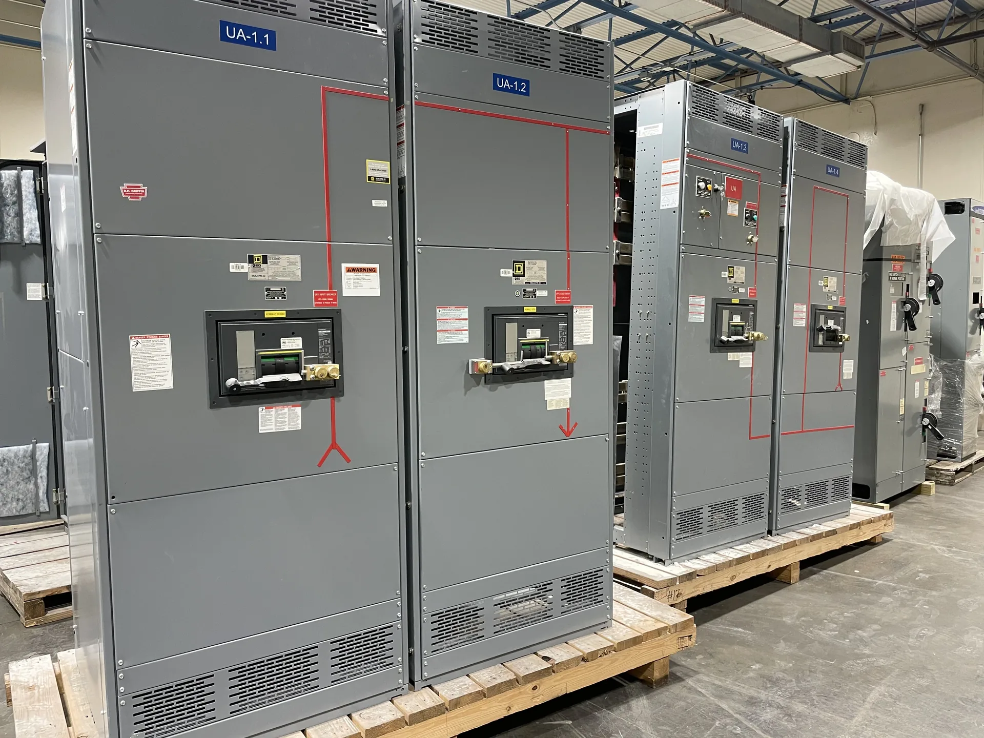
A ground fault is an unintended electrical path between an energized conductor and ground or a grounded conductive part. Its current depends on the system and fault path. Ground-fault detection or protection addresses specified fault conditions; it is distinct from general overload protection and must be selected for the application. A project-specific one-line, load information and physical constraints give the manufacturer a useful basis for discussion. We manufacture and supply new equipment in the United States for projects throughout North Carolina. Ratings and available options must be reviewed against the installation and the required documentation. Discuss your intended schedule and destination when requesting a quotation; lead time and shipping arrangements depend on the final scope.
Ground Fault Glossary Definition — project planning
A short-circuit study estimates the fault current available at points throughout the electrical system. The engineer may need utility source data, transformer ratings and impedances, conductor lengths and sizes, motor contributions, and information about generators or other sources. Different operating configurations can produce different results. Provide the study or the project's specified fault-current requirements with the quote request so the proposed assembly and protective devices can be evaluated against the expected duty. Revisit the study when sources, equipment, or system arrangements change; a preliminary figure is not a substitute for the completed engineering review.
Protection coordination considers how upstream and downstream devices respond to faults and overloads. The goal is often to isolate the affected circuit while keeping as much of the remaining system in service as practical. Where selective coordination is required, the engineer must evaluate the applicable devices across the required range of currents and operating times. Time-current curves, manufacturer coordination tables, available fault current, and actual trip settings may all matter. Share continuity requirements and relevant system information early; a high equipment rating or adjustable trip unit does not by itself prove selective coordination.
Plan Neutral and Grounding Details
Neutral and grounding arrangements affect the equipment design as well as the installation. Identify the system configuration, neutral conductor needs, ground bus, service or feeder application, and any ground-fault protection requirements. The electrical engineer should specify where neutral-to-ground bonding is required and where the neutral must remain isolated, using the adopted code and the actual source configuration. Transformers and generator transfer arrangements can introduce separately derived system questions. Provide these details before drawings are approved, and do not assume that a bonding arrangement suitable at one location is appropriate everywhere downstream.
UL 891 is a safety standard for switchboards; it is not a blanket certification for every product a manufacturer offers. Low-voltage power circuit breaker switchgear is addressed by a different standard, UL 1558, so identify the specified equipment type rather than treating the terms as interchangeable. An individual assembly's certification, voltage, continuous current, and short-circuit ratings depend on its design and applicable certification scope. A manufacturer's UL 891 general coverage program may have limits that differ from those of the standard itself. Request documentation for the specific proposed configuration and its ratings.
Manufacturer and Distributor Roles
A manufacturer designs or assembles new equipment to an agreed configuration and can explain construction, engineering details, and applicable product documentation. A distributor may help customers select and purchase equipment, coordinate orders, and provide a local point of contact. The exact division of work depends on the project and sales channel. Ask who owns the quote, answers technical questions, manages revisions, handles warranty requests, and coordinates delivery. Whether you purchase directly or through a distributor, confirm the named manufacturer and the equipment configuration in the proposal before placing an order.
For projects across the United States, discuss freight requirements before accepting a delivery estimate. Provide the destination, site access restrictions, required delivery window, and whether a loading dock, forklift, or rigging crew is available. Ask how the assembly will be divided and packaged, who arranges unloading, and which freight and insurance terms apply. Confirm any special handling, storage, or weather protection needs with the supplier. On arrival, check the shipment against the packing list and document visible damage on the carrier's paperwork. Report suspected concealed damage promptly under the applicable claim procedures.
Modernization: Designing for Updated Requirements
Modernization can involve supplying a new switchgear or switchboard lineup for a project that needs updated distribution, monitoring, or control functions. The design may incorporate metering, protective relays, communications interfaces, or provisions for future circuits when specified. Each addition needs a defined purpose, power source, wiring interface, and compatibility review. Existing upstream and downstream equipment also influences fault protection and operating sequences. Before the design is finalized, the project team should confirm responsibility for system studies, integration, installation, and acceptance so that new equipment fits the overall plan.
Switchgear can expose workers to shock and arc-flash hazards even after a disconnect has been opened. Installation, testing, operation, and maintenance should be assigned to personnel qualified for the task and the equipment involved. Follow applicable OSHA requirements, the employer's safety procedures, and the equipment instructions. Establish an electrically safe work condition where required: identify all sources, de-energize, apply the required lockout and tagging procedures, and have a qualified person verify absence of voltage. Address stored energy and possible backfeeds. Energized work requires appropriate justification and protective measures under applicable rules.
Review Equipment Drawings
Equipment drawings translate the project requirements into a buildable arrangement. Review the one-line and elevation against the circuit schedule, then check overall dimensions, section splits, mounting details, equipment access, and the location of incoming and outgoing connections. Confirm conductor quantities and sizes, conduit entry areas, bus arrangements, and space for meters or controls. The engineer and installer should compare the drawings with the room layout and other trades before approval. Record questions and revisions in writing; an approved drawing should reflect the configuration being released for manufacture.
Available fault current is a property of the electrical system at a particular point; interrupting and short-circuit ratings describe equipment capability. Check each breaker or fuse's interrupting rating at the applied voltage against the fault current it may need to interrupt. Separately verify the assembly's short-circuit current or withstand rating and any associated time, device or installation conditions. Include contributions from utility sources, generators and motors as applicable to the study. Series-rated device combinations require documented compatibility and application in accordance with their conditions, not an assumption based on individual ampere ratings.
Start with the right specifications
Final capabilities and ratings are confirmed against the application, approved drawings and quotation.
| Project detail | What to provide |
|---|---|
| System | Voltage, phase, wiring and grounding |
| Current | Main and feeder ratings; load information |
| Protection | Available fault current, SCCR and protective device requirements |
| Installation | Enclosure, space, utility requirements and destination |