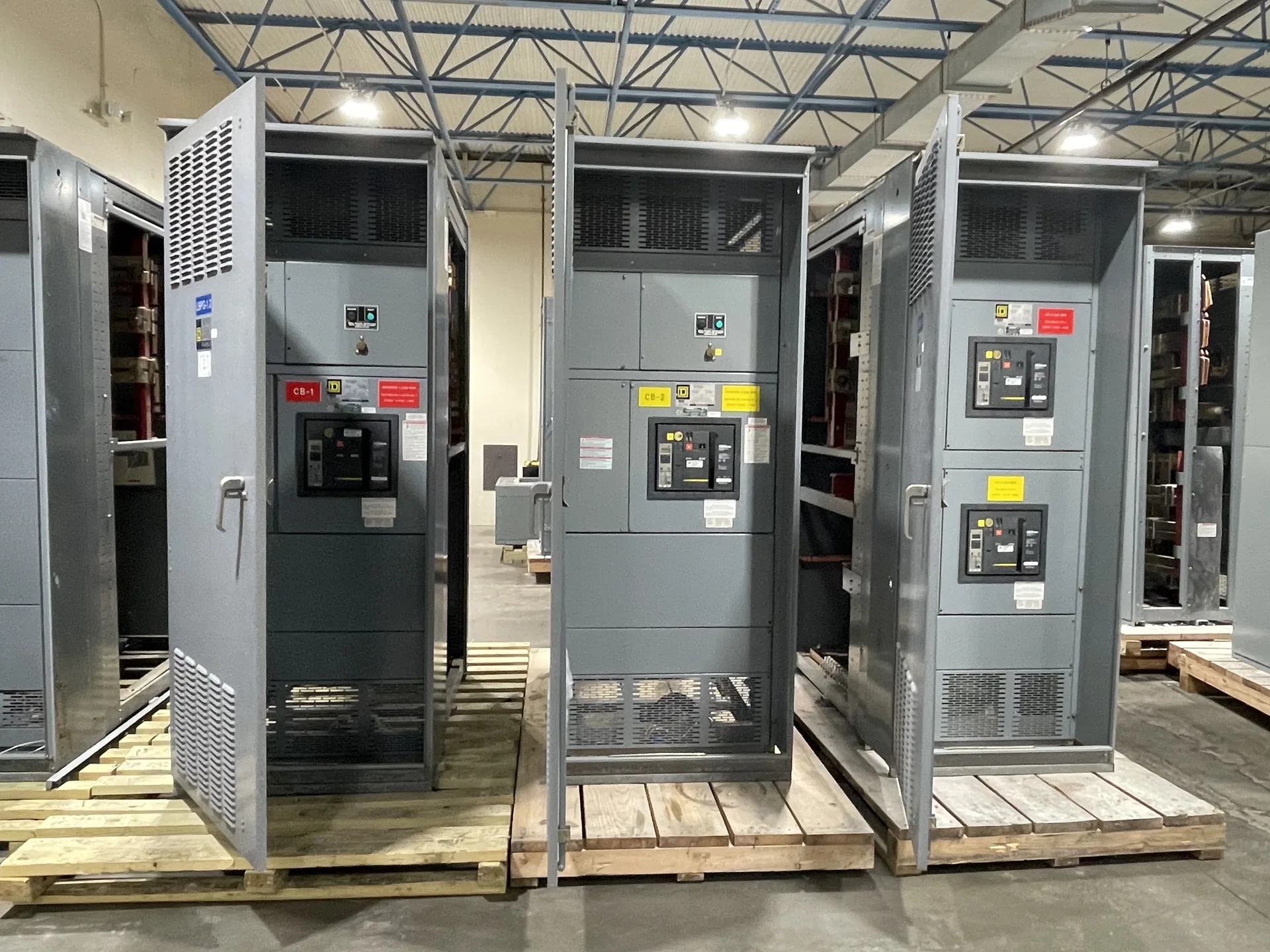
Basic impulse insulation level, or BIL, is a standardized impulse withstand level used to express an insulation system's ability to withstand a specified lightning impulse test. It helps designers coordinate insulation and surge protection. The appropriate BIL depends on equipment voltage class, system exposure, protective devices, and applicable standards. Useful specifications connect the source, protective devices, feeders and physical installation rather than treating each in isolation. Our team builds and supplies new equipment in the USA for North Carolina projects. Provide the information available now, including the intended voltage, current, environment and delivery needs. The engineer of record and the manufacturer can then identify what remains to be clarified before a project-specific quotation.
Basic Impulse Insulation Level Glossary Definition — project planning
Installation planning starts with the approved equipment dimensions, shipping splits, weights, and manufacturer's handling instructions. Check the route from the unloading point to the electrical room, including doors, elevators, floor loading, rigging access, and the final equipment pad or supports. Coordinate conduit locations, cable bending space, grounding, utility interfaces, and any required shutdown with the responsible trades. Define who will store, assemble, install, test, and commission the equipment. Arrange inspections and any required permits before energization. Early coordination can reveal access or sequencing problems while there is still time to address them.
Protection coordination considers how upstream and downstream devices respond to faults and overloads. The goal is often to isolate the affected circuit while keeping as much of the remaining system in service as practical. Where selective coordination is required, the engineer must evaluate the applicable devices across the required range of currents and operating times. Time-current curves, manufacturer coordination tables, available fault current, and actual trip settings may all matter. Share continuity requirements and relevant system information early; a high equipment rating or adjustable trip unit does not by itself prove selective coordination.
SCCR Is Not Interrupting Rating
Short-circuit current rating, or SCCR, describes the fault current an assembly or component can withstand under specified conditions at a stated voltage. A breaker's or fuse's interrupting rating describes the fault current that device can safely interrupt under specified conditions. Both must be considered against the available fault current at the installation point; a high breaker rating alone does not establish the assembly rating. A qualified designer should also review any conditions attached to the equipment rating. Series-rated combinations require specific permitted device combinations and application checks, not an assumption based on the upstream breaker alone.
Changes made after delivery, such as adding devices, altering buswork, or drilling an enclosure outside approved locations, can affect equipment ratings or certification. Before work begins, ask the manufacturer whether the proposed modification is permitted and what documentation or approved components are needed. Discuss the plan with the authority having jurisdiction. A qualified field evaluation body may be needed to assess the modified equipment for the specific installation; the authority decides whether to accept it. A field evaluation is not automatic approval and should not be treated as a substitute for a sound design.
Review Equipment Drawings
Equipment drawings translate the project requirements into a buildable arrangement. Review the one-line and elevation against the circuit schedule, then check overall dimensions, section splits, mounting details, equipment access, and the location of incoming and outgoing connections. Confirm conductor quantities and sizes, conduit entry areas, bus arrangements, and space for meters or controls. The engineer and installer should compare the drawings with the room layout and other trades before approval. Record questions and revisions in writing; an approved drawing should reflect the configuration being released for manufacture.
Load continuity begins with understanding which services can tolerate an interruption and which require an alternate operating plan. Identify critical loads, available sources, transfer arrangements, and dependencies such as control power and cooling. The design team can then evaluate sectionalizing, protective coordination, and maintenance isolation against the project's operating objectives. Procurement documents should describe the intended switching sequence and any interlocks or monitoring interfaces. Backup equipment and redundant paths still require testing, maintenance, and documented operating procedures; neither should be treated as a guarantee of uninterrupted service.
Reserve Working Clearances
Before selecting equipment dimensions, check the electrical room for the working space and access needed around the proposed assembly. Required clearance depends on the applicable code, voltage, equipment arrangement, and conditions at the installation. Door swing, rear access when needed, ventilation, equipment removal, and entry or egress also affect the layout. Compare the manufacturer's drawings with architectural and mechanical plans, including nearby piping and other obstructions. The engineer and authority having jurisdiction should confirm applicable requirements, and the completed working space must remain unobstructed rather than becoming storage.
Electrical verification is selected for the equipment and the project rather than assumed from a generic checklist. Depending on the design, procedures may include continuity checks, control circuit functional tests, and insulation resistance testing where appropriate. Test voltages, temporary disconnections, and sensitive electronic components must be addressed in the written procedure and equipment instructions. Results should be recorded with the applicable acceptance criteria and any corrective action. Routine production or field tests should not be represented as substitutes for the design evaluation or short-circuit testing needed to support an equipment rating.
Arrange Nationwide Shipping
For projects across the United States, discuss freight requirements before accepting a delivery estimate. Provide the destination, site access restrictions, required delivery window, and whether a loading dock, forklift, or rigging crew is available. Ask how the assembly will be divided and packaged, who arranges unloading, and which freight and insurance terms apply. Confirm any special handling, storage, or weather protection needs with the supplier. On arrival, check the shipment against the packing list and document visible damage on the carrier's paperwork. Report suspected concealed damage promptly under the applicable claim procedures.
Control and metering wiring connects devices such as relays, switches, indicators, and instrument transformers to the functions shown on the project drawings. Conductor size, insulation, terminal selection, and routing should reflect circuit ratings and the installation environment. Labels at both ends make circuits easier to trace during startup and future maintenance. Separation and mechanical support can reduce interference and protect wiring from sharp edges or moving parts. Particular care is needed with current transformer secondary circuits: their connections and test procedures must follow the equipment instructions and applicable safety practices.
Start with the right specifications
Final capabilities and ratings are confirmed against the application, approved drawings and quotation.
| Project detail | What to provide |
|---|---|
| System | Voltage, phase, wiring and grounding |
| Current | Main and feeder ratings; load information |
| Protection | Available fault current, SCCR and protective device requirements |
| Installation | Enclosure, space, utility requirements and destination |