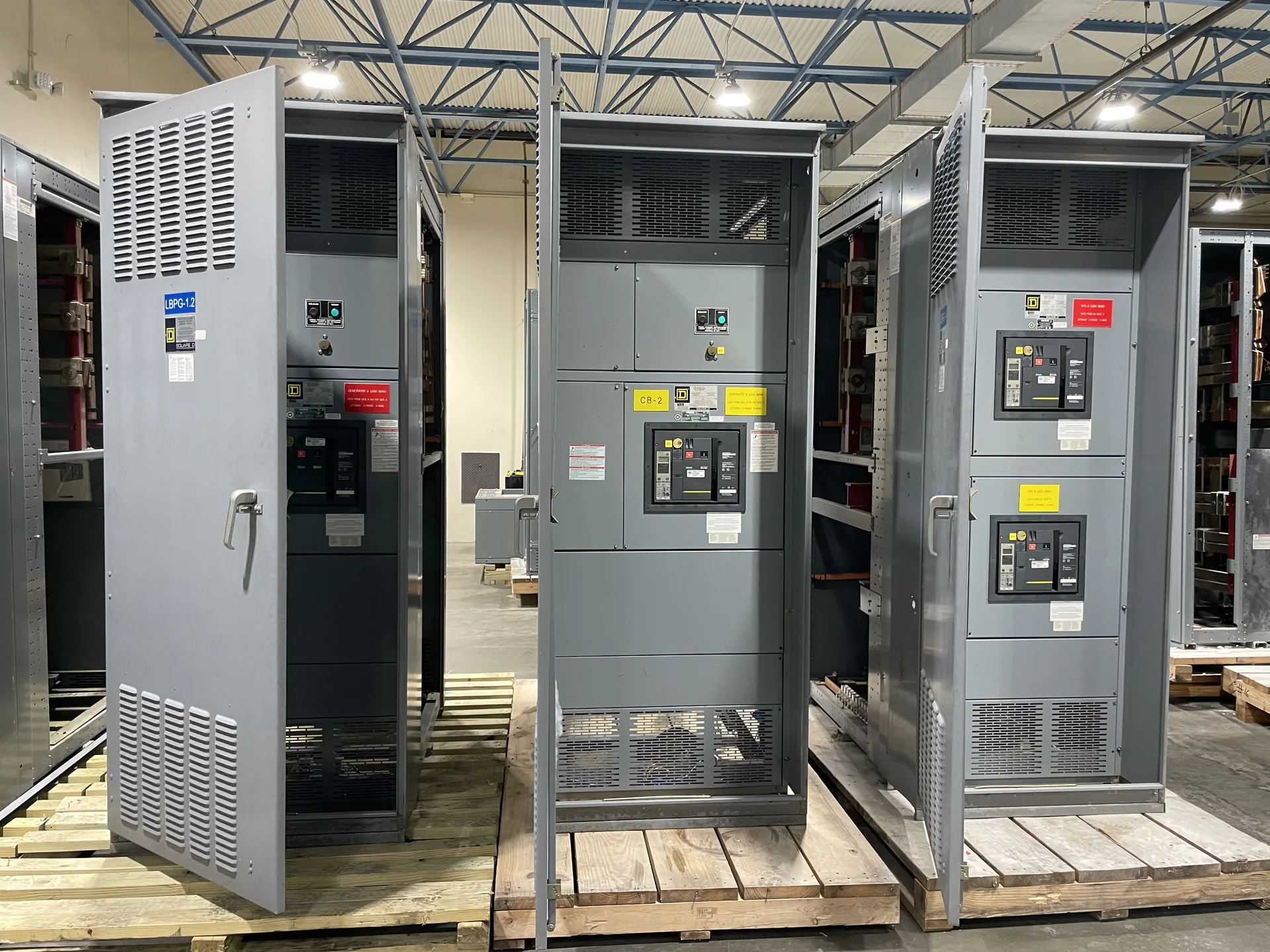
An automatic transfer switch is equipment that transfers a connected load between power sources automatically according to its control logic. It monitors source conditions and initiates transfer and retransfer when its programmed criteria are satisfied. Transition type, timing, source controls, and protective-device coordination depend on the particular system design. A clear request gives the manufacturer a way to assess electrical ratings, physical fit, operating needs and delivery together. We build and supply new equipment in the USA for projects across North Carolina. Begin with the information you have, then identify outstanding items with the design team. Specifications, listing requirements, project timing and shipping are confirmed as part of the quotation and engineering review.
Automatic Transfer Switch Glossary Definition — project planning
An automatic transfer switch selects between normal and alternate sources according to the project's transfer sequence. Define source voltages, phase rotation, load current, generator starting signals, retransfer settings and whether open-transition or another transfer method is needed. The engineer should determine whether the neutral is switched based on the grounding arrangement and applicable requirements. Check the switch's withstand and closing rating against available fault current from each source, the specified upstream protection and applicable time limitations. Identify any service-entrance use and request documentation for the specified equipment standard, such as UL 1008.
Load continuity begins with understanding which services can tolerate an interruption and which require an alternate operating plan. Identify critical loads, available sources, transfer arrangements, and dependencies such as control power and cooling. The design team can then evaluate sectionalizing, protective coordination, and maintenance isolation against the project's operating objectives. Procurement documents should describe the intended switching sequence and any interlocks or monitoring interfaces. Backup equipment and redundant paths still require testing, maintenance, and documented operating procedures; neither should be treated as a guarantee of uninterrupted service.
Phase Design and Load Balance
Phase design should begin with the source configuration and the voltage and phase requirements of the connected loads. Distinguish single-phase and three-phase loads, identify any neutral requirements, and provide the engineer with a realistic load schedule. Distribution planning should consider phase balance, nonlinear loads, conductor sizing, grounding, and the effect of motor starting on the system. Where multiple sources or transfer equipment are involved, document the neutral switching and grounding approach for coordinated review. Procurement drawings should communicate phase arrangement and termination requirements clearly to the installation team.
A motor control center groups motor starters and related control equipment so multiple motors can be operated and protected from an organized lineup. Provide a motor schedule with horsepower, voltage, full-load current, starting method and duty for each load. Specify disconnects, overload protection, starter type, control voltage and any variable-frequency drives or communication interfaces. Review heat dissipation, available fault current, feeder sizing and space for future units. Drawout construction, network features and spare compartments should be confirmed for the proposed design rather than assumed from the term MCC.
Evaluate Field Modifications
Changes made after delivery, such as adding devices, altering buswork, or drilling an enclosure outside approved locations, can affect equipment ratings or certification. Before work begins, ask the manufacturer whether the proposed modification is permitted and what documentation or approved components are needed. Discuss the plan with the authority having jurisdiction. A qualified field evaluation body may be needed to assess the modified equipment for the specific installation; the authority decides whether to accept it. A field evaluation is not automatic approval and should not be treated as a substitute for a sound design.
Switchgear can expose workers to shock and arc-flash hazards even after a disconnect has been opened. Installation, testing, operation, and maintenance should be assigned to personnel qualified for the task and the equipment involved. Follow applicable OSHA requirements, the employer's safety procedures, and the equipment instructions. Establish an electrically safe work condition where required: identify all sources, de-energize, apply the required lockout and tagging procedures, and have a qualified person verify absence of voltage. Address stored energy and possible backfeeds. Energized work requires appropriate justification and protective measures under applicable rules.
Manufacturer and Distributor Roles
A manufacturer designs or assembles new equipment to an agreed configuration and can explain construction, engineering details, and applicable product documentation. A distributor may help customers select and purchase equipment, coordinate orders, and provide a local point of contact. The exact division of work depends on the project and sales channel. Ask who owns the quote, answers technical questions, manages revisions, handles warranty requests, and coordinates delivery. Whether you purchase directly or through a distributor, confirm the named manufacturer and the equipment configuration in the proposal before placing an order.
A submittal package gives the design and construction teams an opportunity to check the proposed equipment against the project documents. Depending on the contract, it may include drawings, device data sheets, ratings, enclosure details, metering information, and certification documentation. Agree on the required contents and the review sequence before ordering. The engineer, contractor, owner, and utility may each need to review different items. Consolidate comments, track revisions, and return a clear disposition to the supplier. Submittal review does not replace the separate inspections and approvals required for installation.
Project Drawings and Submittals
Clear drawings help a switchgear supplier and the design team resolve interfaces before equipment is released for fabrication. Include a current one-line diagram, source information, feeder schedule, short-circuit study assumptions when available, and the intended control and metering functions. Physical drawings should identify room dimensions, cable entry, equipment clearances, and relevant obstructions. Request submittals that show lineup arrangement, connection details, device functions, and proposed departures from the specification. Review comments should be reconciled with the engineer of record and other affected trades before fabrication proceeds.
Installation planning starts with the approved equipment dimensions, shipping splits, weights, and manufacturer's handling instructions. Check the route from the unloading point to the electrical room, including doors, elevators, floor loading, rigging access, and the final equipment pad or supports. Coordinate conduit locations, cable bending space, grounding, utility interfaces, and any required shutdown with the responsible trades. Define who will store, assemble, install, test, and commission the equipment. Arrange inspections and any required permits before energization. Early coordination can reveal access or sequencing problems while there is still time to address them.
Start with the right specifications
Final capabilities and ratings are confirmed against the application, approved drawings and quotation.
| Project detail | What to provide |
|---|---|
| System | Voltage, phase, wiring and grounding |
| Current | Main and feeder ratings; load information |
| Protection | Available fault current, SCCR and protective device requirements |
| Installation | Enclosure, space, utility requirements and destination |