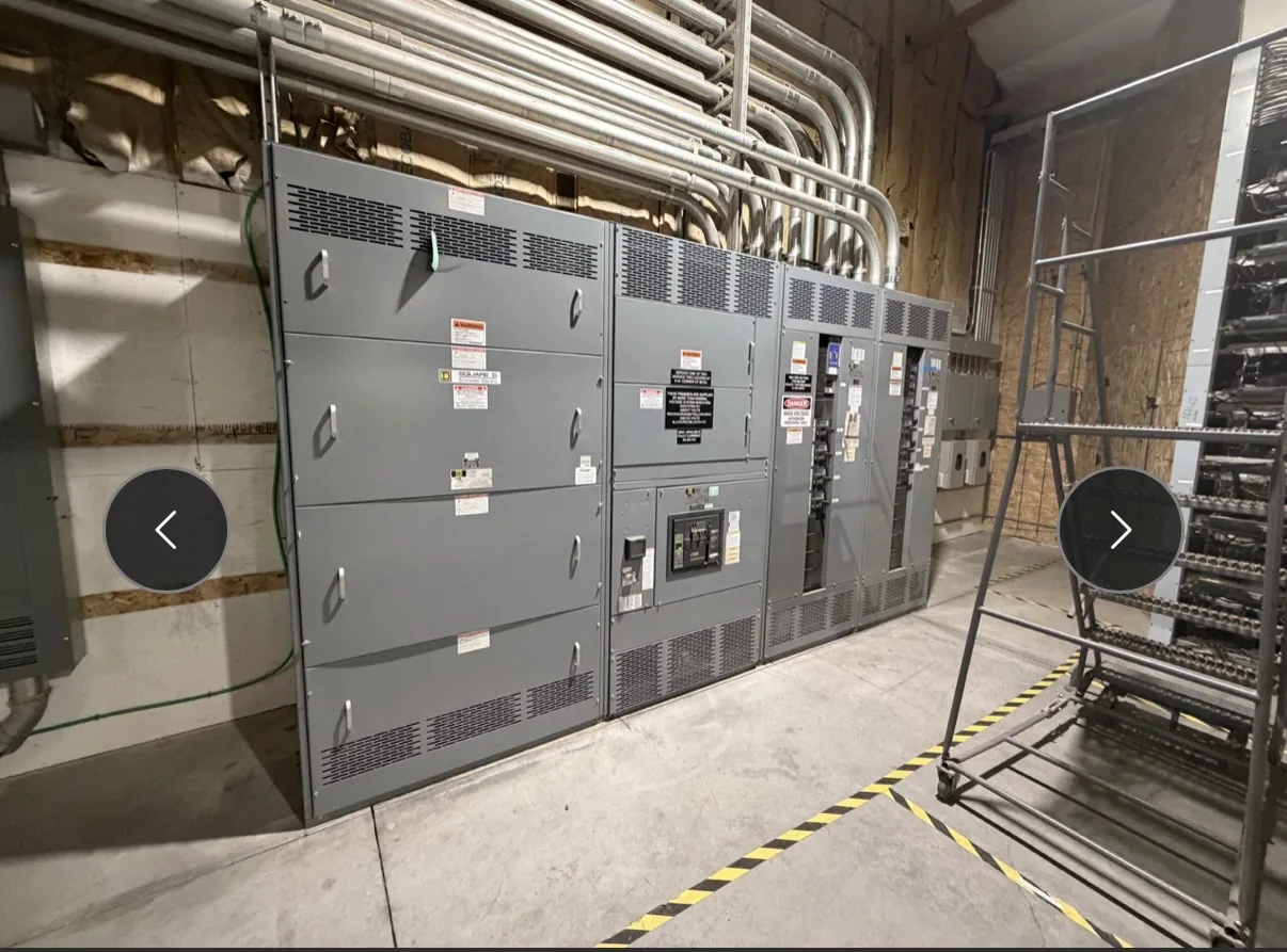
Available fault current is the prospective current that could flow at a specific point in a power system if a fault occurred. Source capacity and the impedance of transformers, conductors, and other upstream components affect its value. A site-specific calculation supports selection of equipment withstand and protective-device interrupting ratings. Useful specifications connect the source, protective devices, feeders and physical installation rather than treating each in isolation. Our team builds and supplies new equipment in the USA for North Carolina projects. Provide the information available now, including the intended voltage, current, environment and delivery needs. The engineer of record and the manufacturer can then identify what remains to be clarified before a project-specific quotation.
Available Fault Current Glossary Definition — project planning
A short-circuit study estimates the fault current available at points throughout the electrical system. The engineer may need utility source data, transformer ratings and impedances, conductor lengths and sizes, motor contributions, and information about generators or other sources. Different operating configurations can produce different results. Provide the study or the project's specified fault-current requirements with the quote request so the proposed assembly and protective devices can be evaluated against the expected duty. Revisit the study when sources, equipment, or system arrangements change; a preliminary figure is not a substitute for the completed engineering review.
Short-circuit current rating, or SCCR, describes the fault current an assembly or component can withstand under specified conditions at a stated voltage. A breaker's or fuse's interrupting rating describes the fault current that device can safely interrupt under specified conditions. Both must be considered against the available fault current at the installation point; a high breaker rating alone does not establish the assembly rating. A qualified designer should also review any conditions attached to the equipment rating. Series-rated combinations require specific permitted device combinations and application checks, not an assumption based on the upstream breaker alone.
Coordinate Protective Devices
Protection coordination considers how upstream and downstream devices respond to faults and overloads. The goal is often to isolate the affected circuit while keeping as much of the remaining system in service as practical. Where selective coordination is required, the engineer must evaluate the applicable devices across the required range of currents and operating times. Time-current curves, manufacturer coordination tables, available fault current, and actual trip settings may all matter. Share continuity requirements and relevant system information early; a high equipment rating or adjustable trip unit does not by itself prove selective coordination.
A useful quote request begins with the latest one-line diagram, project location, system voltage, phase and wire configuration, and required continuous current. Include available fault current or the engineer's required short-circuit rating, the number and ratings of incoming and outgoing circuits, and whether the equipment serves as service entrance or downstream distribution. Share enclosure requirements, metering, communications, spare capacity, and preferred delivery dates. Attach specifications and identify open questions rather than guessing. A complete package helps the manufacturer identify assumptions, compare options, and return a quote suited to the new equipment your project needs.
Project Drawings and Submittals
Clear drawings help a switchgear supplier and the design team resolve interfaces before equipment is released for fabrication. Include a current one-line diagram, source information, feeder schedule, short-circuit study assumptions when available, and the intended control and metering functions. Physical drawings should identify room dimensions, cable entry, equipment clearances, and relevant obstructions. Request submittals that show lineup arrangement, connection details, device functions, and proposed departures from the specification. Review comments should be reconciled with the engineer of record and other affected trades before fabrication proceeds.
Before selecting equipment dimensions, check the electrical room for the working space and access needed around the proposed assembly. Required clearance depends on the applicable code, voltage, equipment arrangement, and conditions at the installation. Door swing, rear access when needed, ventilation, equipment removal, and entry or egress also affect the layout. Compare the manufacturer's drawings with architectural and mechanical plans, including nearby piping and other obstructions. The engineer and authority having jurisdiction should confirm applicable requirements, and the completed working space must remain unobstructed rather than becoming storage.
Manufacturer and Distributor Roles
A manufacturer designs or assembles new equipment to an agreed configuration and can explain construction, engineering details, and applicable product documentation. A distributor may help customers select and purchase equipment, coordinate orders, and provide a local point of contact. The exact division of work depends on the project and sales channel. Ask who owns the quote, answers technical questions, manages revisions, handles warranty requests, and coordinates delivery. Whether you purchase directly or through a distributor, confirm the named manufacturer and the equipment configuration in the proposal before placing an order.
A lead-time estimate is more useful when its starting point and milestones are clear. Ask whether the estimate begins at order acceptance, receipt of required commercial information, approval of drawings, or release for production. Break the schedule into engineering, customer review, component procurement, assembly, inspection, and freight. Breakers, metering, special enclosures, and design changes can affect the schedule, as can delayed approvals. Share the required on-site date and any outage or construction constraints. Request an updated schedule when assumptions change, and distinguish an estimate from a confirmed commitment.
Custom Design: Establishing the Electrical Basis
A useful switchgear design starts with the electrical system, not the enclosure dimensions alone. The project team establishes nominal voltage, frequency, phase configuration, grounding method, expected loads, and available fault current at the installation point. These inputs guide equipment ratings, protective device selection, and the arrangement of incoming and outgoing circuits. Future feeders or alternate sources should be identified early because they can affect bus capacity and layout. The final design must also reflect the applicable codes, the site conditions, and the ratings of the complete assembly.
A retrofit project may call for new equipment that connects to an existing electrical system while respecting established building constraints. Useful starting information includes current single-line drawings, available fault current, feeder sizes, connection locations, and the physical route into the room. Existing records should be checked against verified site conditions because past modifications may not appear on drawings. The new assembly's ratings and interfaces must be evaluated for the intended installation. Outage sequencing and the boundaries between the new equipment and existing infrastructure should be agreed with the project team.
Start with the right specifications
Final capabilities and ratings are confirmed against the application, approved drawings and quotation.
| Project detail | What to provide |
|---|---|
| System | Voltage, phase, wiring and grounding |
| Current | Main and feeder ratings; load information |
| Protection | Available fault current, SCCR and protective device requirements |
| Installation | Enclosure, space, utility requirements and destination |