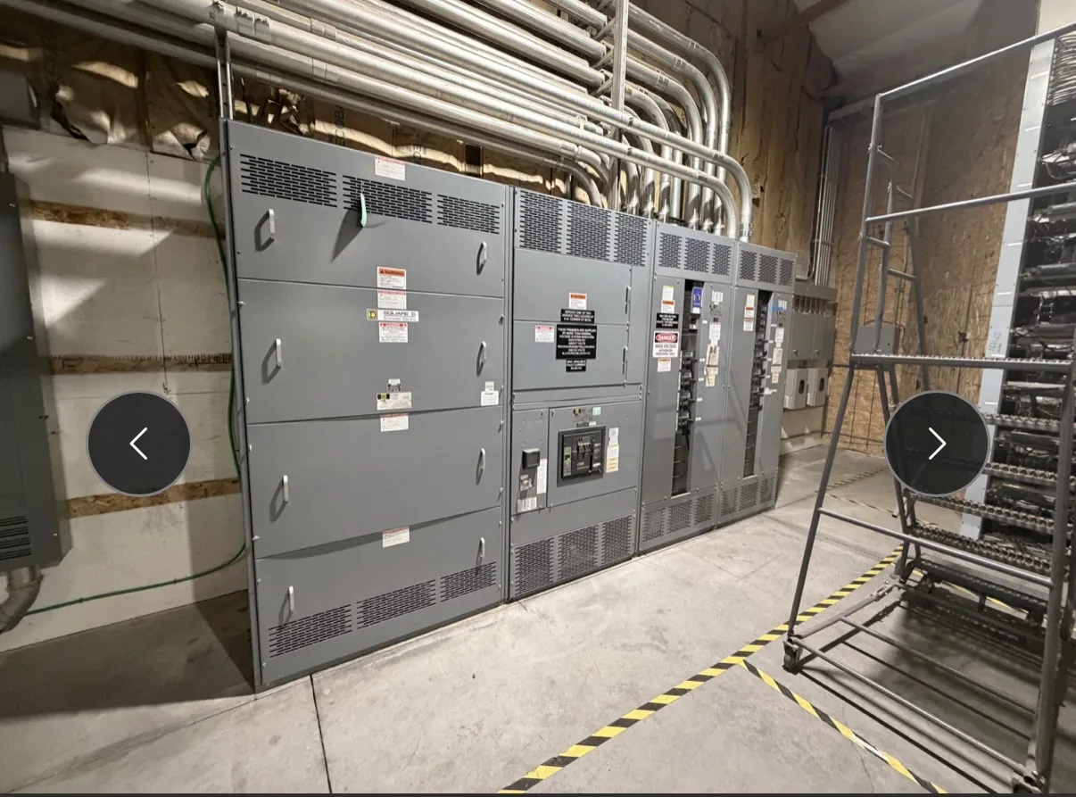
Plan textile facilities power distribution for a project in Raleigh, North Carolina, focusing on spinning, weaving or finishing loads, motor control, environmental exposure, and existing equipment condition. Confirm the serving utility, permit authority, and requirements for occupied-site upgrades. Confirm site-specific loads, the serving utility, local approvals, and equipment scope rather than assuming local availability. A project-specific one-line, load information and physical constraints give the manufacturer a useful basis for discussion. We manufacture and supply new equipment in the United States for projects throughout North Carolina. Ratings and available options must be reviewed against the installation and the required documentation. Discuss your intended schedule and destination when requesting a quotation; lead time and shipping arrangements depend on the final scope.
Textile Facilities Switchgear in Raleigh NC — project planning
A motor control center groups motor starters and related control equipment so multiple motors can be operated and protected from an organized lineup. Provide a motor schedule with horsepower, voltage, full-load current, starting method and duty for each load. Specify disconnects, overload protection, starter type, control voltage and any variable-frequency drives or communication interfaces. Review heat dissipation, available fault current, feeder sizing and space for future units. Drawout construction, network features and spare compartments should be confirmed for the proposed design rather than assumed from the term MCC.
Textile operations can combine many motor-driven machines with air handling and other continuous production loads. Develop a feeder schedule that distinguishes individual machine groups, ventilation, and support systems, and review motor starting and drive characteristics with the design team. Lint, dust, humidity, and cleaning practices should inform the equipment location and enclosure requirements. Procurement documents should describe access for inspection, cable routing, and the desired means of isolating machine groups. Coordinate electrical maintenance with production and housekeeping practices so switchgear access does not depend on congested storage areas.
Phase Design and Load Balance
Phase design should begin with the source configuration and the voltage and phase requirements of the connected loads. Distinguish single-phase and three-phase loads, identify any neutral requirements, and provide the engineer with a realistic load schedule. Distribution planning should consider phase balance, nonlinear loads, conductor sizing, grounding, and the effect of motor starting on the system. Where multiple sources or transfer equipment are involved, document the neutral switching and grounding approach for coordinated review. Procurement drawings should communicate phase arrangement and termination requirements clearly to the installation team.
Utility-facing switchgear projects require early coordination over the boundary between the utility system and customer-owned distribution. The procurement package should identify the point of connection, incoming source characteristics, metering arrangements, protection responsibilities, and the information needed for the utility's review. Show current and voltage transformer locations where applicable, along with communication and control interfaces. Confirm assumptions about available fault current and future system changes with the responsible parties. Clear ownership and operating responsibilities help avoid gaps when equipment is commissioned, switched, or maintained.
Project Drawings and Submittals
Clear drawings help a switchgear supplier and the design team resolve interfaces before equipment is released for fabrication. Include a current one-line diagram, source information, feeder schedule, short-circuit study assumptions when available, and the intended control and metering functions. Physical drawings should identify room dimensions, cable entry, equipment clearances, and relevant obstructions. Request submittals that show lineup arrangement, connection details, device functions, and proposed departures from the specification. Review comments should be reconciled with the engineer of record and other affected trades before fabrication proceeds.
Load continuity begins with understanding which services can tolerate an interruption and which require an alternate operating plan. Identify critical loads, available sources, transfer arrangements, and dependencies such as control power and cooling. The design team can then evaluate sectionalizing, protective coordination, and maintenance isolation against the project's operating objectives. Procurement documents should describe the intended switching sequence and any interlocks or monitoring interfaces. Backup equipment and redundant paths still require testing, maintenance, and documented operating procedures; neither should be treated as a guarantee of uninterrupted service.
Wiring: Controls, Metering, and Identification
Control and metering wiring connects devices such as relays, switches, indicators, and instrument transformers to the functions shown on the project drawings. Conductor size, insulation, terminal selection, and routing should reflect circuit ratings and the installation environment. Labels at both ends make circuits easier to trace during startup and future maintenance. Separation and mechanical support can reduce interference and protect wiring from sharp edges or moving parts. Particular care is needed with current transformer secondary circuits: their connections and test procedures must follow the equipment instructions and applicable safety practices.
A commissioning plan should define what is tested, who performs each step, and what evidence is needed for acceptance. Depending on the equipment and project, checks may include device operation, control sequences, metering signals, alarms, and communication with the facility system. Qualified personnel should use procedures appropriate to the equipment and coordinate any energization with the site owner and other responsible parties. Handover documents can include final drawings, test records, equipment instructions, and a list of unresolved items. Actual testing and services depend on the agreed project scope.
Maintenance Access and Safe Isolation
Switchgear layouts should give qualified personnel a practical way to inspect, test, isolate, and maintain equipment over its service life. Show required working space, door swing, cable access, and the route for removing major components on the project drawings. Identify isolation points and any alternate feeds or control-power sources that could leave parts energized. Procurement specifications can request durable labeling, accessible test provisions, and documentation of operating sequences. Maintenance plans should use site-specific procedures for controlling hazardous energy and verifying absence of voltage before work begins.
UL 891 is a standard for dead-front switchboards rated 1,000 volts or less. It is not the standard used to establish requirements for switchgear rated above 1,000 volts; that equipment requires consideration of other applicable standards and ratings. For a switchboard project, the specified voltage, continuous current, short-circuit current rating, and intended service conditions must match the application. A UL 891 listing must not be assumed from the use of listed components or the mention of the standard. Verify any claimed listing for the actual assembly using its markings and certification documentation.
Start with the right specifications
Final capabilities and ratings are confirmed against the application, approved drawings and quotation.
| Project detail | What to provide |
|---|---|
| System | Voltage, phase, wiring and grounding |
| Current | Main and feeder ratings; load information |
| Protection | Available fault current, SCCR and protective device requirements |
| Installation | Enclosure, space, utility requirements and destination |