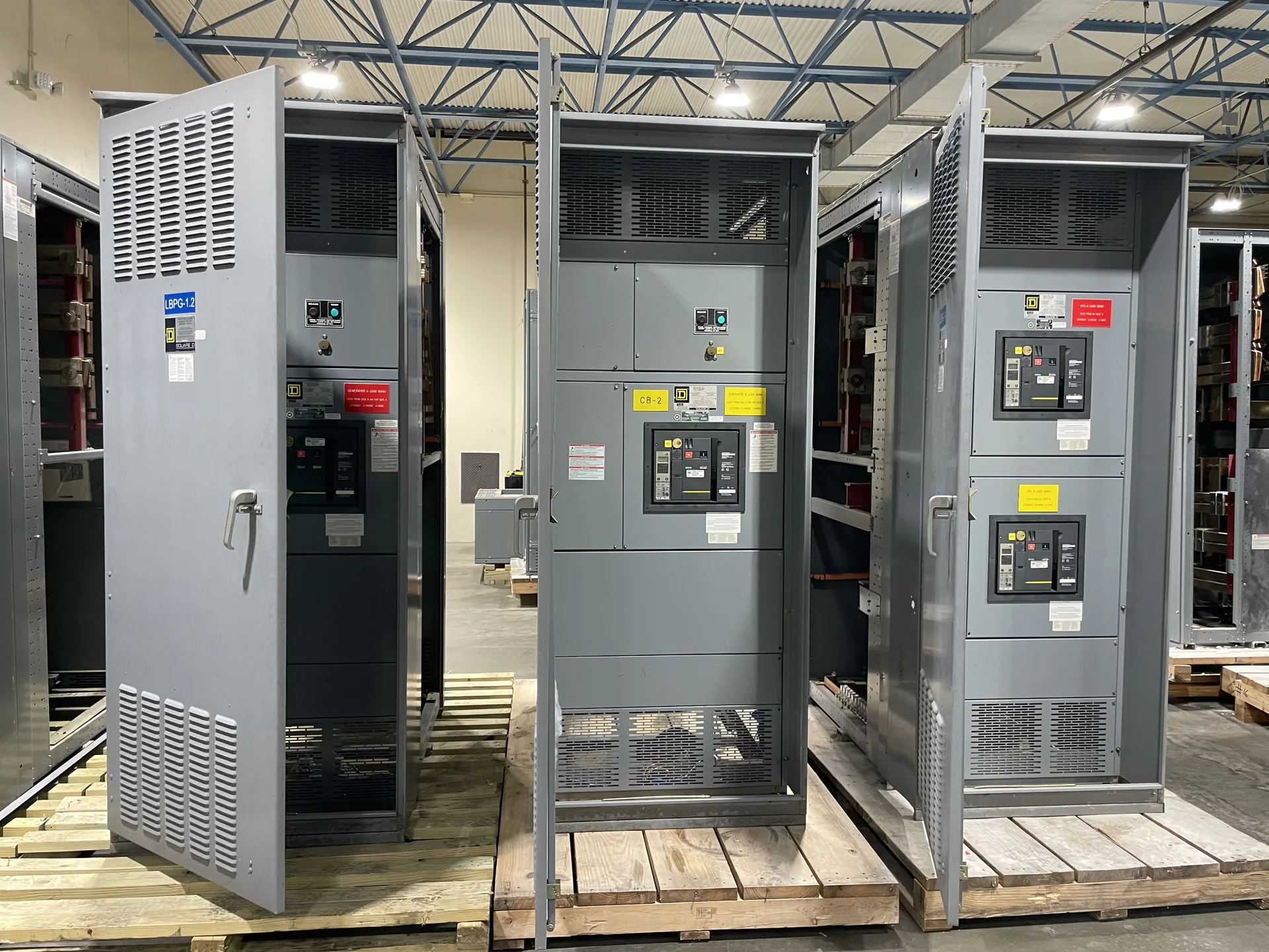
Review dryer motor and heating loads, protective coordination, safety controls, and operating duty for the actual equipment. The starting point is the actual electrical system and how the lineup will be installed and operated. We build and supply new power distribution equipment in the United States for North Carolina projects. Share the intended ratings, application, available space and schedule with our team so they can be evaluated against the proposed scope. The final configuration, availability and delivery details are established in the project quotation.
Textile Drying Equipment Distribution — project planning
A motor control center groups motor starters and related control equipment so multiple motors can be operated and protected from an organized lineup. Provide a motor schedule with horsepower, voltage, full-load current, starting method and duty for each load. Specify disconnects, overload protection, starter type, control voltage and any variable-frequency drives or communication interfaces. Review heat dissipation, available fault current, feeder sizing and space for future units. Drawout construction, network features and spare compartments should be confirmed for the proposed design rather than assumed from the term MCC.
Load continuity begins with understanding which services can tolerate an interruption and which require an alternate operating plan. Identify critical loads, available sources, transfer arrangements, and dependencies such as control power and cooling. The design team can then evaluate sectionalizing, protective coordination, and maintenance isolation against the project's operating objectives. Procurement documents should describe the intended switching sequence and any interlocks or monitoring interfaces. Backup equipment and redundant paths still require testing, maintenance, and documented operating procedures; neither should be treated as a guarantee of uninterrupted service.
Textile Facility Power Distribution
Textile operations can combine many motor-driven machines with air handling and other continuous production loads. Develop a feeder schedule that distinguishes individual machine groups, ventilation, and support systems, and review motor starting and drive characteristics with the design team. Lint, dust, humidity, and cleaning practices should inform the equipment location and enclosure requirements. Procurement documents should describe access for inspection, cable routing, and the desired means of isolating machine groups. Coordinate electrical maintenance with production and housekeeping practices so switchgear access does not depend on congested storage areas.
Phase design should begin with the source configuration and the voltage and phase requirements of the connected loads. Distinguish single-phase and three-phase loads, identify any neutral requirements, and provide the engineer with a realistic load schedule. Distribution planning should consider phase balance, nonlinear loads, conductor sizing, grounding, and the effect of motor starting on the system. Where multiple sources or transfer equipment are involved, document the neutral switching and grounding approach for coordinated review. Procurement drawings should communicate phase arrangement and termination requirements clearly to the installation team.
Inspection and Testing: Electrical Verification
Electrical verification is selected for the equipment and the project rather than assumed from a generic checklist. Depending on the design, procedures may include continuity checks, control circuit functional tests, and insulation resistance testing where appropriate. Test voltages, temporary disconnections, and sensitive electronic components must be addressed in the written procedure and equipment instructions. Results should be recorded with the applicable acceptance criteria and any corrective action. Routine production or field tests should not be represented as substitutes for the design evaluation or short-circuit testing needed to support an equipment rating.
Commissioning brings the equipment and the wider installation together through a planned sequence of checks before service. The project team should confirm anchorage, accessible clearances, cable terminations, grounding, section splices, and control connections against the drawings and installation instructions. Utility interfaces, protective device settings, and remote signals may require coordination with other parties. Responsibilities for tests, documentation, and energization should be established in advance. Work on electrical equipment must follow applicable safety requirements, including deenergization, lockout or tagging, and verification of the deenergized condition where required.
Modernization: Designing for Updated Requirements
Modernization can involve supplying a new switchgear or switchboard lineup for a project that needs updated distribution, monitoring, or control functions. The design may incorporate metering, protective relays, communications interfaces, or provisions for future circuits when specified. Each addition needs a defined purpose, power source, wiring interface, and compatibility review. Existing upstream and downstream equipment also influences fault protection and operating sequences. Before the design is finalized, the project team should confirm responsibility for system studies, integration, installation, and acceptance so that new equipment fits the overall plan.
Protection coordination considers how upstream and downstream devices respond to faults and overloads. The goal is often to isolate the affected circuit while keeping as much of the remaining system in service as practical. Where selective coordination is required, the engineer must evaluate the applicable devices across the required range of currents and operating times. Time-current curves, manufacturer coordination tables, available fault current, and actual trip settings may all matter. Share continuity requirements and relevant system information early; a high equipment rating or adjustable trip unit does not by itself prove selective coordination.
Use Qualified Electrical Personnel
Switchgear can expose workers to shock and arc-flash hazards even after a disconnect has been opened. Installation, testing, operation, and maintenance should be assigned to personnel qualified for the task and the equipment involved. Follow applicable OSHA requirements, the employer's safety procedures, and the equipment instructions. Establish an electrically safe work condition where required: identify all sources, de-energize, apply the required lockout and tagging procedures, and have a qualified person verify absence of voltage. Address stored energy and possible backfeeds. Energized work requires appropriate justification and protective measures under applicable rules.
A short-circuit study estimates the fault current available at points throughout the electrical system. The engineer may need utility source data, transformer ratings and impedances, conductor lengths and sizes, motor contributions, and information about generators or other sources. Different operating configurations can produce different results. Provide the study or the project's specified fault-current requirements with the quote request so the proposed assembly and protective devices can be evaluated against the expected duty. Revisit the study when sources, equipment, or system arrangements change; a preliminary figure is not a substitute for the completed engineering review.
Start with the right specifications
Final capabilities and ratings are confirmed against the application, approved drawings and quotation.
| Project detail | What to provide |
|---|---|
| System | Voltage, phase, wiring and grounding |
| Current | Main and feeder ratings; load information |
| Protection | Available fault current, SCCR and protective device requirements |
| Installation | Enclosure, space, utility requirements and destination |