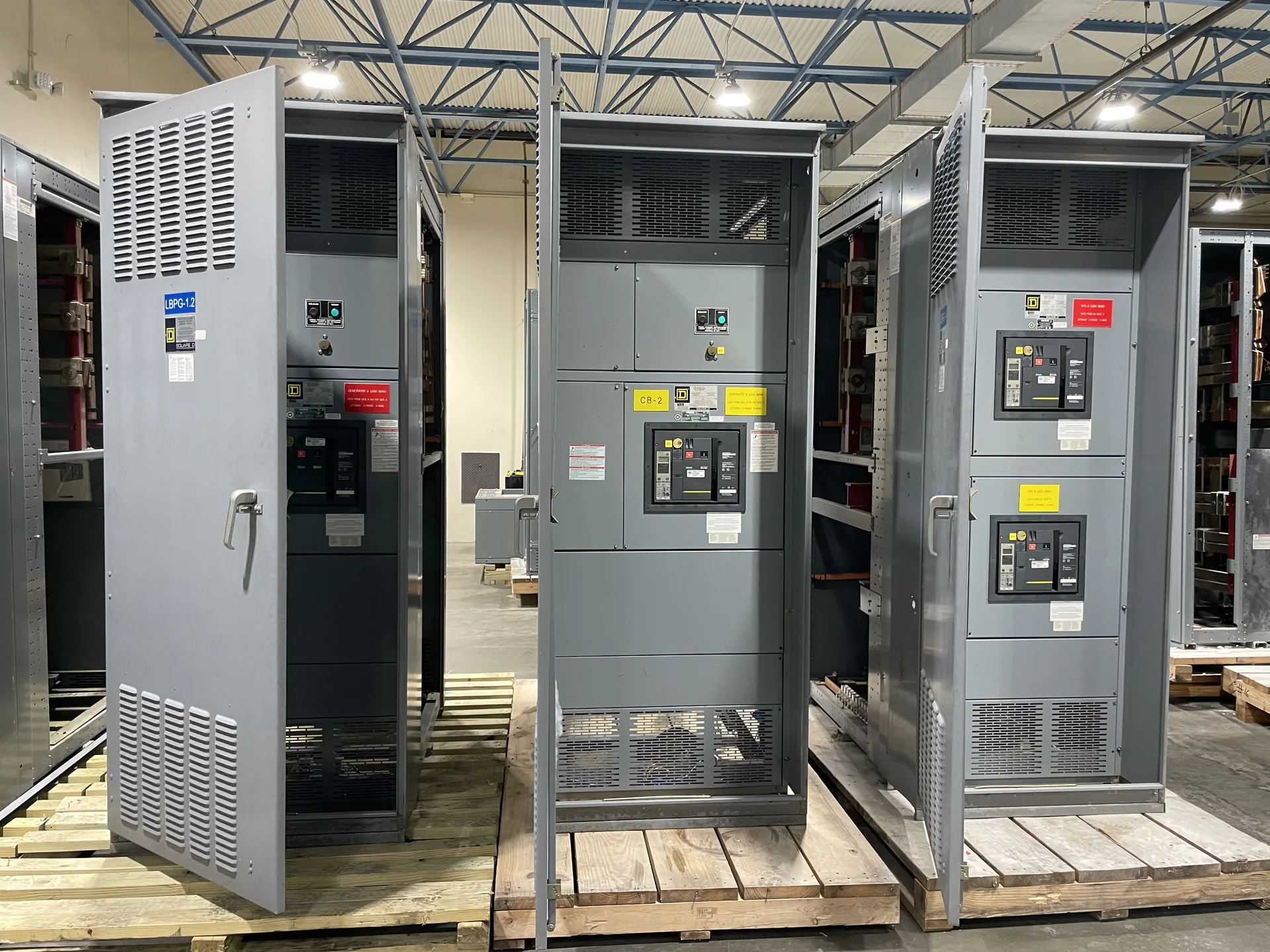
Identify conductor size, material, number, temperature rating, tightening instructions, and equipment approval as lug-selection inputs. The equipment selection should follow the actual source characteristics, connected loads, operating requirements and installation environment. We manufacture new power distribution equipment in the United States and serve customers across North Carolina. Tell us what is known about the one-line, desired configuration and target delivery schedule. A project review establishes the proposed scope and identifies ratings or documentation that need confirmation.
Switchgear Terminal Lug Specifications — project planning
Enclosure selection starts with the actual location and exposure, not simply an indoor or outdoor label. Specify ambient temperature, altitude, humidity, dust, corrosive agents, water exposure and any washdown or ventilation needs. NEMA Type 1 is generally intended for indoor use, while Type 3R is commonly selected for certain outdoor weather exposures; confirm that the chosen type meets the full site conditions. Account for heaters, drainage, cable entry, working clearances and maintenance access where applicable. An environmental enclosure rating alone does not establish an arc-resistant rating or a specific equipment certification.
For 27 kV and 35 kV medium-voltage applications, provide the actual system nominal and maximum operating voltages rather than relying on a class label alone. The equipment's rated maximum voltage and insulation withstand levels must suit the supply and the applicable standard. Share available short-circuit current, grounding information, feeder duties and the utility's protection and metering requirements. Cable termination space, surge protection, outdoor exposure and required isolation also influence the layout. Confirm the exact switching devices, ratings and interface details for the proposed equipment before finalizing the specification.
5 kV and 15 kV Project Inputs
For 5 kV and 15 kV medium-voltage projects, distinguish the system's nominal voltage from the equipment's rated maximum voltage. Provide the operating voltage range, frequency, grounding method, insulation requirements and available short-circuit current at the proposed connection. Protection may involve circuit breakers and relays or switches and fuses, depending on the application. Identify the utility interface, cable type, termination arrangement and any metering requirements. Before selecting an assembly, confirm that its continuous current, dielectric withstand and interrupting or fault-withstand ratings match the specific system and applicable standard.
Available fault current is a property of the electrical system at a particular point; interrupting and short-circuit ratings describe equipment capability. Check each breaker or fuse's interrupting rating at the applied voltage against the fault current it may need to interrupt. Separately verify the assembly's short-circuit current or withstand rating and any associated time, device or installation conditions. Include contributions from utility sources, generators and motors as applicable to the study. Series-rated device combinations require documented compatibility and application in accordance with their conditions, not an assumption based on individual ampere ratings.
Inspection and Testing: Verifying Assembly Details
Inspection provides a structured way to compare an assembled lineup with its approved drawings and component instructions. A review can include device identification, conductor routing, barriers, grounding connections, hardware, labels, and the condition of the enclosure. Mechanical checks may cover door operation, interlocks, and the fit of removable sections where applicable. Findings should be documented and resolved before release. The inspection scope and acceptance criteria belong in the project documentation, because a visual check alone cannot establish every electrical rating or demonstrate performance under fault conditions.
Sheet metal fabrication turns an equipment layout into the structural and protective enclosure around electrical components. Cutouts, formed panels, mounting surfaces, doors, and covers must align with the intended devices and cable paths. Material selection and finish depend on the specified environment, including indoor or outdoor exposure and corrosion concerns. Edges and openings should be finished to avoid damage to conductors and injury during handling. Enclosure modifications can affect strength, protection, ventilation, or a documented rating, so changes require review against the applicable design and instructions.
Busbar Work: Conductors and Support
Busbars distribute power within an assembly and must be designed as part of the complete electrical system. Conductor material, cross section, temperature rise, spacing, insulation, and support arrangement all affect suitability for the intended duty. The design must also account for mechanical forces associated with the specified short-circuit rating. Bending, punching, and routing should follow the approved construction details rather than rules of thumb alone. Phase identification and clear section interfaces help installers connect a lineup correctly while preserving required clearances and access.
A short-circuit study estimates the fault current available at points throughout the electrical system. The engineer may need utility source data, transformer ratings and impedances, conductor lengths and sizes, motor contributions, and information about generators or other sources. Different operating configurations can produce different results. Provide the study or the project's specified fault-current requirements with the quote request so the proposed assembly and protective devices can be evaluated against the expected duty. Revisit the study when sources, equipment, or system arrangements change; a preliminary figure is not a substitute for the completed engineering review.
Project Location and Shipping
Location affects both switchgear design inputs and the practical work of getting equipment to its installation point. Identify indoor or outdoor placement, environmental exposure, site elevation, seismic design criteria where relevant, and any unusual transportation restrictions. The procurement package should describe delivery access, unloading responsibilities, storage conditions, and the available path through doors or other openings. Discuss shipping splits and field assembly requirements with the project team before finalizing the layout. Protect equipment from moisture and physical damage during transit and storage, following the applicable handling instructions.
A useful quote request begins with the latest one-line diagram, project location, system voltage, phase and wire configuration, and required continuous current. Include available fault current or the engineer's required short-circuit rating, the number and ratings of incoming and outgoing circuits, and whether the equipment serves as service entrance or downstream distribution. Share enclosure requirements, metering, communications, spare capacity, and preferred delivery dates. Attach specifications and identify open questions rather than guessing. A complete package helps the manufacturer identify assumptions, compare options, and return a quote suited to the new equipment your project needs.
Start with the right specifications
Final capabilities and ratings are confirmed against the application, approved drawings and quotation.
| Project detail | What to provide |
|---|---|
| System | Voltage, phase, wiring and grounding |
| Current | Main and feeder ratings; load information |
| Protection | Available fault current, SCCR and protective device requirements |
| Installation | Enclosure, space, utility requirements and destination |