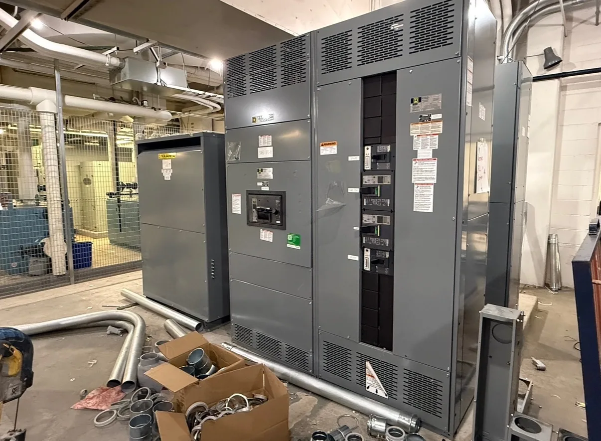
Consider power-distribution project planning in Greensboro, North Carolina. Check delivery access, existing service documentation, and potential production outage windows. Verify utility, permitting, site conditions, and equipment availability for the actual address. Useful specifications connect the source, protective devices, feeders and physical installation rather than treating each in isolation. Our team builds and supplies new equipment in the USA for North Carolina projects. Provide the information available now, including the intended voltage, current, environment and delivery needs. The engineer of record and the manufacturer can then identify what remains to be clarified before a project-specific quotation.
Switchgear in Greensboro NC — project planning
Switchgear layouts should give qualified personnel a practical way to inspect, test, isolate, and maintain equipment over its service life. Show required working space, door swing, cable access, and the route for removing major components on the project drawings. Identify isolation points and any alternate feeds or control-power sources that could leave parts energized. Procurement specifications can request durable labeling, accessible test provisions, and documentation of operating sequences. Maintenance plans should use site-specific procedures for controlling hazardous energy and verifying absence of voltage before work begins.
Service-entrance equipment connects the utility supply to a facility's distribution system and must be coordinated with the utility and the authority having jurisdiction. Establish the service voltage, available fault current, point of connection, metering arrangement, conductor entry and service disconnect configuration early. Specify whether the assembly must be suitable for use as service equipment and verify the proposed markings and documentation. Grounding and neutral bonding must follow the applicable code and the actual service arrangement. Include utility access, required clearances and any restrictions on customer-installed metering or protective devices.
Commissioning: Coordinating the Site Interfaces
Commissioning brings the equipment and the wider installation together through a planned sequence of checks before service. The project team should confirm anchorage, accessible clearances, cable terminations, grounding, section splices, and control connections against the drawings and installation instructions. Utility interfaces, protective device settings, and remote signals may require coordination with other parties. Responsibilities for tests, documentation, and energization should be established in advance. Work on electrical equipment must follow applicable safety requirements, including deenergization, lockout or tagging, and verification of the deenergized condition where required.
A retrofit project may call for new equipment that connects to an existing electrical system while respecting established building constraints. Useful starting information includes current single-line drawings, available fault current, feeder sizes, connection locations, and the physical route into the room. Existing records should be checked against verified site conditions because past modifications may not appear on drawings. The new assembly's ratings and interfaces must be evaluated for the intended installation. Outage sequencing and the boundaries between the new equipment and existing infrastructure should be agreed with the project team.
Project Drawings and Submittals
Clear drawings help a switchgear supplier and the design team resolve interfaces before equipment is released for fabrication. Include a current one-line diagram, source information, feeder schedule, short-circuit study assumptions when available, and the intended control and metering functions. Physical drawings should identify room dimensions, cable entry, equipment clearances, and relevant obstructions. Request submittals that show lineup arrangement, connection details, device functions, and proposed departures from the specification. Review comments should be reconciled with the engineer of record and other affected trades before fabrication proceeds.
Before selecting equipment dimensions, check the electrical room for the working space and access needed around the proposed assembly. Required clearance depends on the applicable code, voltage, equipment arrangement, and conditions at the installation. Door swing, rear access when needed, ventilation, equipment removal, and entry or egress also affect the layout. Compare the manufacturer's drawings with architectural and mechanical plans, including nearby piping and other obstructions. The engineer and authority having jurisdiction should confirm applicable requirements, and the completed working space must remain unobstructed rather than becoming storage.
Load Continuity and Switching
Load continuity begins with understanding which services can tolerate an interruption and which require an alternate operating plan. Identify critical loads, available sources, transfer arrangements, and dependencies such as control power and cooling. The design team can then evaluate sectionalizing, protective coordination, and maintenance isolation against the project's operating objectives. Procurement documents should describe the intended switching sequence and any interlocks or monitoring interfaces. Backup equipment and redundant paths still require testing, maintenance, and documented operating procedures; neither should be treated as a guarantee of uninterrupted service.
A lead-time estimate is more useful when its starting point and milestones are clear. Ask whether the estimate begins at order acceptance, receipt of required commercial information, approval of drawings, or release for production. Break the schedule into engineering, customer review, component procurement, assembly, inspection, and freight. Breakers, metering, special enclosures, and design changes can affect the schedule, as can delayed approvals. Share the required on-site date and any outage or construction constraints. Request an updated schedule when assumptions change, and distinguish an estimate from a confirmed commitment.
Understand Switchgear Pricing Inputs
The price of new distribution equipment depends on its electrical ratings, physical construction, and included components. Main and feeder device types, bus material and capacity, short-circuit requirements, enclosure rating, metering, controls, and spare provisions can all affect the proposal. Engineering, testing, special documentation, freight, and site services may be included or quoted separately. Provide comparable specifications to each supplier and review exclusions, alternates, and payment terms alongside the base price. If the design is incomplete, ask which assumptions are driving the estimate and what could change when the drawings are finalized.
Enclosure selection starts with the actual location and exposure, not simply an indoor or outdoor label. Specify ambient temperature, altitude, humidity, dust, corrosive agents, water exposure and any washdown or ventilation needs. NEMA Type 1 is generally intended for indoor use, while Type 3R is commonly selected for certain outdoor weather exposures; confirm that the chosen type meets the full site conditions. Account for heaters, drainage, cable entry, working clearances and maintenance access where applicable. An environmental enclosure rating alone does not establish an arc-resistant rating or a specific equipment certification.
Start with the right specifications
Final capabilities and ratings are confirmed against the application, approved drawings and quotation.
| Project detail | What to provide |
|---|---|
| System | Voltage, phase, wiring and grounding |
| Current | Main and feeder ratings; load information |
| Protection | Available fault current, SCCR and protective device requirements |
| Installation | Enclosure, space, utility requirements and destination |