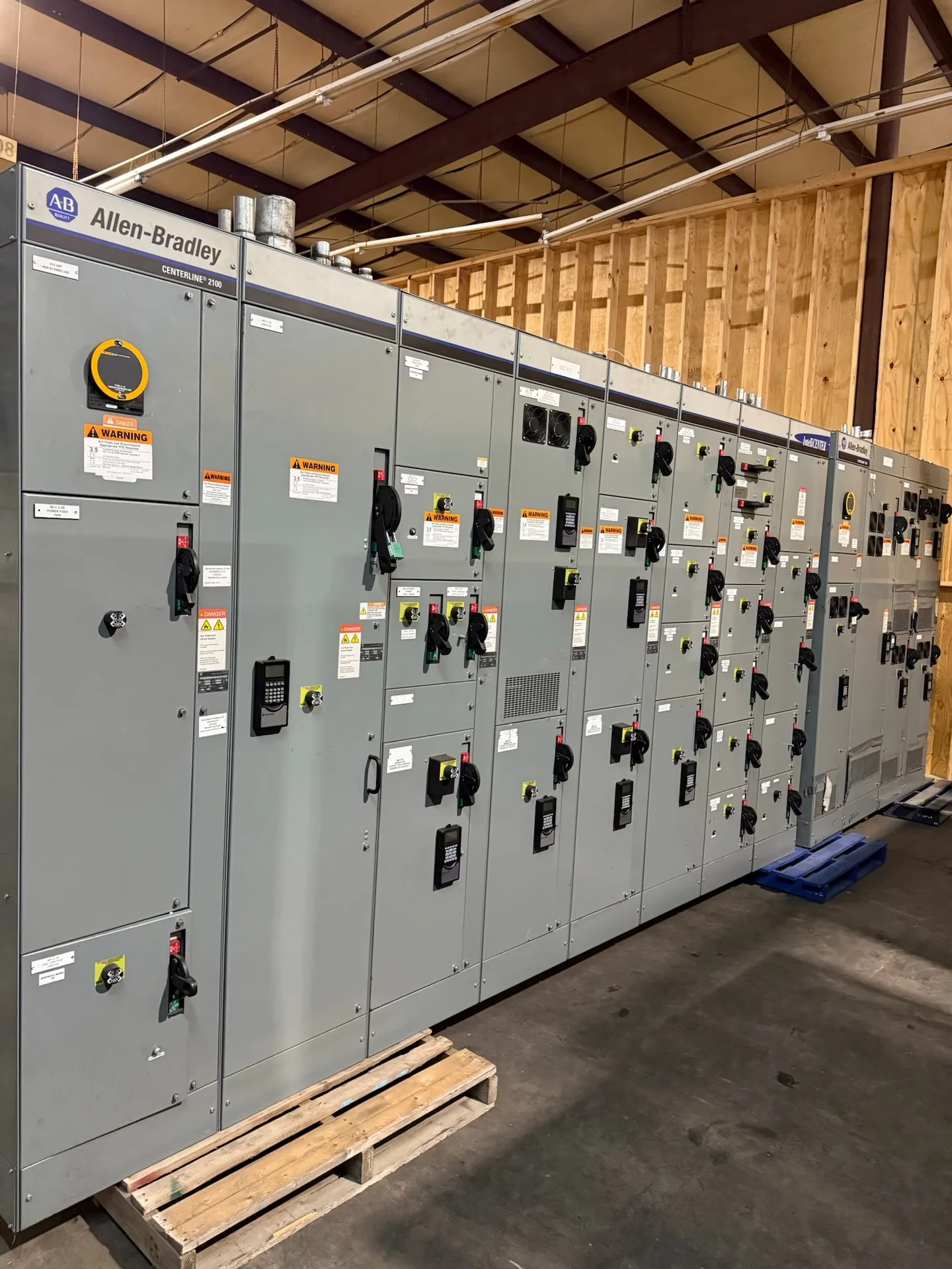
Identify the drawings, electrical ratings, enclosure, testing, shipping, and schedule details needed for an informed custom-equipment price request. A project-specific one-line, load information and physical constraints give the manufacturer a useful basis for discussion. We manufacture and supply new equipment in the United States for projects throughout North Carolina. Ratings and available options must be reviewed against the installation and the required documentation. Discuss your intended schedule and destination when requesting a quotation; lead time and shipping arrangements depend on the final scope.
Request Custom Switchgear Pricing — project planning
Inspection provides a structured way to compare an assembled lineup with its approved drawings and component instructions. A review can include device identification, conductor routing, barriers, grounding connections, hardware, labels, and the condition of the enclosure. Mechanical checks may cover door operation, interlocks, and the fit of removable sections where applicable. Findings should be documented and resolved before release. The inspection scope and acceptance criteria belong in the project documentation, because a visual check alone cannot establish every electrical rating or demonstrate performance under fault conditions.
The price of new distribution equipment depends on its electrical ratings, physical construction, and included components. Main and feeder device types, bus material and capacity, short-circuit requirements, enclosure rating, metering, controls, and spare provisions can all affect the proposal. Engineering, testing, special documentation, freight, and site services may be included or quoted separately. Provide comparable specifications to each supplier and review exclusions, alternates, and payment terms alongside the base price. If the design is incomplete, ask which assumptions are driving the estimate and what could change when the drawings are finalized.
Prepare a Switchgear Quote Request
A useful quote request begins with the latest one-line diagram, project location, system voltage, phase and wire configuration, and required continuous current. Include available fault current or the engineer's required short-circuit rating, the number and ratings of incoming and outgoing circuits, and whether the equipment serves as service entrance or downstream distribution. Share enclosure requirements, metering, communications, spare capacity, and preferred delivery dates. Attach specifications and identify open questions rather than guessing. A complete package helps the manufacturer identify assumptions, compare options, and return a quote suited to the new equipment your project needs.
Equipment drawings translate the project requirements into a buildable arrangement. Review the one-line and elevation against the circuit schedule, then check overall dimensions, section splits, mounting details, equipment access, and the location of incoming and outgoing connections. Confirm conductor quantities and sizes, conduit entry areas, bus arrangements, and space for meters or controls. The engineer and installer should compare the drawings with the room layout and other trades before approval. Record questions and revisions in writing; an approved drawing should reflect the configuration being released for manufacture.
Sheet Metal Fabrication: Enclosures and Access
Sheet metal fabrication turns an equipment layout into the structural and protective enclosure around electrical components. Cutouts, formed panels, mounting surfaces, doors, and covers must align with the intended devices and cable paths. Material selection and finish depend on the specified environment, including indoor or outdoor exposure and corrosion concerns. Edges and openings should be finished to avoid damage to conductors and injury during handling. Enclosure modifications can affect strength, protection, ventilation, or a documented rating, so changes require review against the applicable design and instructions.
Before selecting equipment dimensions, check the electrical room for the working space and access needed around the proposed assembly. Required clearance depends on the applicable code, voltage, equipment arrangement, and conditions at the installation. Door swing, rear access when needed, ventilation, equipment removal, and entry or egress also affect the layout. Compare the manufacturer's drawings with architectural and mechanical plans, including nearby piping and other obstructions. The engineer and authority having jurisdiction should confirm applicable requirements, and the completed working space must remain unobstructed rather than becoming storage.
Find the Right Supplier
Start with suppliers that offer the type of new equipment and voltage class specified for your project. Give each candidate the same one-line, specifications, delivery location, and schedule so their proposals can be compared fairly. Ask about design support, the proposed assembly's ratings and certification, component sourcing, documentation, and warranty process. Request confirmation of the sales channel and the person responsible for changes after order placement. Evaluate technical fit and responsiveness as well as price; a proposal that clearly identifies assumptions and exclusions is easier for your project team to review.
A useful switchgear design starts with the electrical system, not the enclosure dimensions alone. The project team establishes nominal voltage, frequency, phase configuration, grounding method, expected loads, and available fault current at the installation point. These inputs guide equipment ratings, protective device selection, and the arrangement of incoming and outgoing circuits. Future feeders or alternate sources should be identified early because they can affect bus capacity and layout. The final design must also reflect the applicable codes, the site conditions, and the ratings of the complete assembly.
Plan Neutral and Grounding Details
Neutral and grounding arrangements affect the equipment design as well as the installation. Identify the system configuration, neutral conductor needs, ground bus, service or feeder application, and any ground-fault protection requirements. The electrical engineer should specify where neutral-to-ground bonding is required and where the neutral must remain isolated, using the adopted code and the actual source configuration. Transformers and generator transfer arrangements can introduce separately derived system questions. Provide these details before drawings are approved, and do not assume that a bonding arrangement suitable at one location is appropriate everywhere downstream.
A project-specific equipment layout connects electrical requirements to the space available for installation and maintenance. Section dimensions, cable entry, conductor bending space, ventilation, and access to operating devices all influence the arrangement. The design should account for doors, removable covers, lifting provisions, and the working clearances required at the installed location. Coordination with the building team helps identify obstructions, floor loading, and the route into the electrical room. A documented layout also makes it easier to review future expansion without assuming unused space is automatically suitable for additional equipment.
Start with the right specifications
Final capabilities and ratings are confirmed against the application, approved drawings and quotation.
| Project detail | What to provide |
|---|---|
| System | Voltage, phase, wiring and grounding |
| Current | Main and feeder ratings; load information |
| Protection | Available fault current, SCCR and protective device requirements |
| Installation | Enclosure, space, utility requirements and destination |