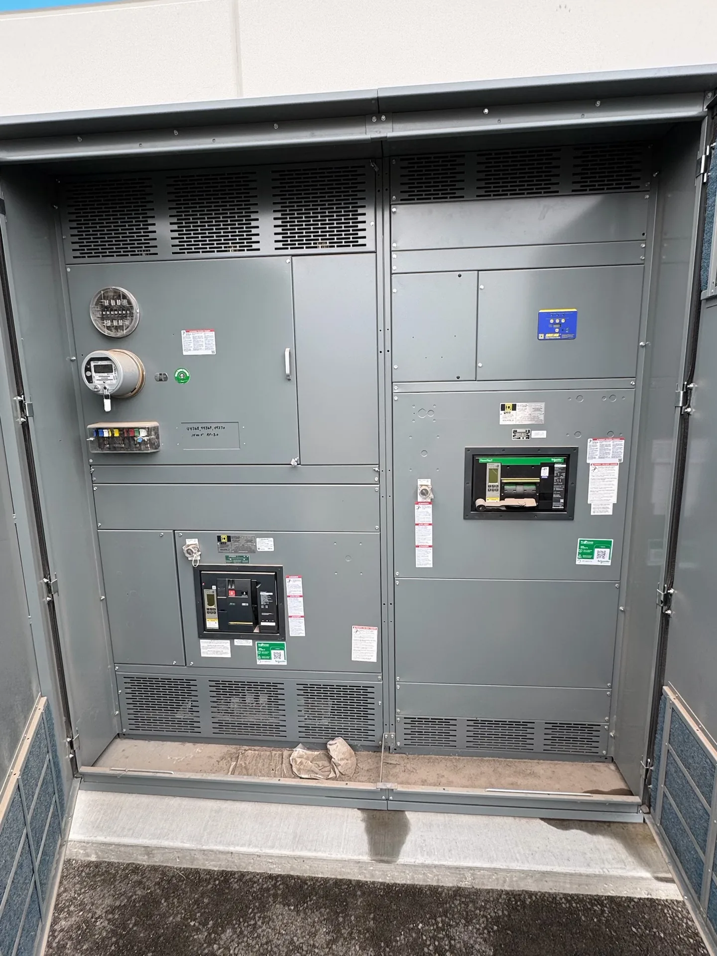
Plan power plants power distribution for a project in Charlotte, North Carolina, focusing on generator and station-service interfaces, auxiliary motors, protection, and controlled operating sequences. Review utility service boundaries and electrical-room access for the project address. Confirm site-specific loads, the serving utility, local approvals, and equipment scope rather than assuming local availability. The starting point is the actual electrical system and how the lineup will be installed and operated. We build and supply new power distribution equipment in the United States for North Carolina projects. Share the intended ratings, application, available space and schedule with our team so they can be evaluated against the proposed scope. The final configuration, availability and delivery details are established in the project quotation.
Power Plants Switchgear in Charlotte NC — project planning
Utility-facing switchgear projects require early coordination over the boundary between the utility system and customer-owned distribution. The procurement package should identify the point of connection, incoming source characteristics, metering arrangements, protection responsibilities, and the information needed for the utility's review. Show current and voltage transformer locations where applicable, along with communication and control interfaces. Confirm assumptions about available fault current and future system changes with the responsible parties. Clear ownership and operating responsibilities help avoid gaps when equipment is commissioned, switched, or maintained.
Power plant distribution may serve generating equipment, auxiliary motors, control systems, and other loads that support plant operation. Define normal and alternate sources, operating modes, and the sequence for energizing auxiliaries when preparing a switchgear specification. Protective relaying, interlocks, and control power should be evaluated as an integrated scheme rather than selected independently. Procurement documents should identify interface points with generators, transformers, and supervisory controls, as applicable. Maintenance planning should also address isolation, stored energy, and verification of de-energization before personnel work on equipment.
Commissioning: Coordinating the Site Interfaces
Commissioning brings the equipment and the wider installation together through a planned sequence of checks before service. The project team should confirm anchorage, accessible clearances, cable terminations, grounding, section splices, and control connections against the drawings and installation instructions. Utility interfaces, protective device settings, and remote signals may require coordination with other parties. Responsibilities for tests, documentation, and energization should be established in advance. Work on electrical equipment must follow applicable safety requirements, including deenergization, lockout or tagging, and verification of the deenergized condition where required.
Switchgear layouts should give qualified personnel a practical way to inspect, test, isolate, and maintain equipment over its service life. Show required working space, door swing, cable access, and the route for removing major components on the project drawings. Identify isolation points and any alternate feeds or control-power sources that could leave parts energized. Procurement specifications can request durable labeling, accessible test provisions, and documentation of operating sequences. Maintenance plans should use site-specific procedures for controlling hazardous energy and verifying absence of voltage before work begins.
Modernization: Designing for Updated Requirements
Modernization can involve supplying a new switchgear or switchboard lineup for a project that needs updated distribution, monitoring, or control functions. The design may incorporate metering, protective relays, communications interfaces, or provisions for future circuits when specified. Each addition needs a defined purpose, power source, wiring interface, and compatibility review. Existing upstream and downstream equipment also influences fault protection and operating sequences. Before the design is finalized, the project team should confirm responsibility for system studies, integration, installation, and acceptance so that new equipment fits the overall plan.
Neutral and grounding arrangements affect the equipment design as well as the installation. Identify the system configuration, neutral conductor needs, ground bus, service or feeder application, and any ground-fault protection requirements. The electrical engineer should specify where neutral-to-ground bonding is required and where the neutral must remain isolated, using the adopted code and the actual source configuration. Transformers and generator transfer arrangements can introduce separately derived system questions. Provide these details before drawings are approved, and do not assume that a bonding arrangement suitable at one location is appropriate everywhere downstream.
Project Drawings and Submittals
Clear drawings help a switchgear supplier and the design team resolve interfaces before equipment is released for fabrication. Include a current one-line diagram, source information, feeder schedule, short-circuit study assumptions when available, and the intended control and metering functions. Physical drawings should identify room dimensions, cable entry, equipment clearances, and relevant obstructions. Request submittals that show lineup arrangement, connection details, device functions, and proposed departures from the specification. Review comments should be reconciled with the engineer of record and other affected trades before fabrication proceeds.
Sheet metal fabrication turns an equipment layout into the structural and protective enclosure around electrical components. Cutouts, formed panels, mounting surfaces, doors, and covers must align with the intended devices and cable paths. Material selection and finish depend on the specified environment, including indoor or outdoor exposure and corrosion concerns. Edges and openings should be finished to avoid damage to conductors and injury during handling. Enclosure modifications can affect strength, protection, ventilation, or a documented rating, so changes require review against the applicable design and instructions.
Review Equipment Drawings
Equipment drawings translate the project requirements into a buildable arrangement. Review the one-line and elevation against the circuit schedule, then check overall dimensions, section splits, mounting details, equipment access, and the location of incoming and outgoing connections. Confirm conductor quantities and sizes, conduit entry areas, bus arrangements, and space for meters or controls. The engineer and installer should compare the drawings with the room layout and other trades before approval. Record questions and revisions in writing; an approved drawing should reflect the configuration being released for manufacture.
A motor control center groups motor starters and related control equipment so multiple motors can be operated and protected from an organized lineup. Provide a motor schedule with horsepower, voltage, full-load current, starting method and duty for each load. Specify disconnects, overload protection, starter type, control voltage and any variable-frequency drives or communication interfaces. Review heat dissipation, available fault current, feeder sizing and space for future units. Drawout construction, network features and spare compartments should be confirmed for the proposed design rather than assumed from the term MCC.
Start with the right specifications
Final capabilities and ratings are confirmed against the application, approved drawings and quotation.
| Project detail | What to provide |
|---|---|
| System | Voltage, phase, wiring and grounding |
| Current | Main and feeder ratings; load information |
| Protection | Available fault current, SCCR and protective device requirements |
| Installation | Enclosure, space, utility requirements and destination |