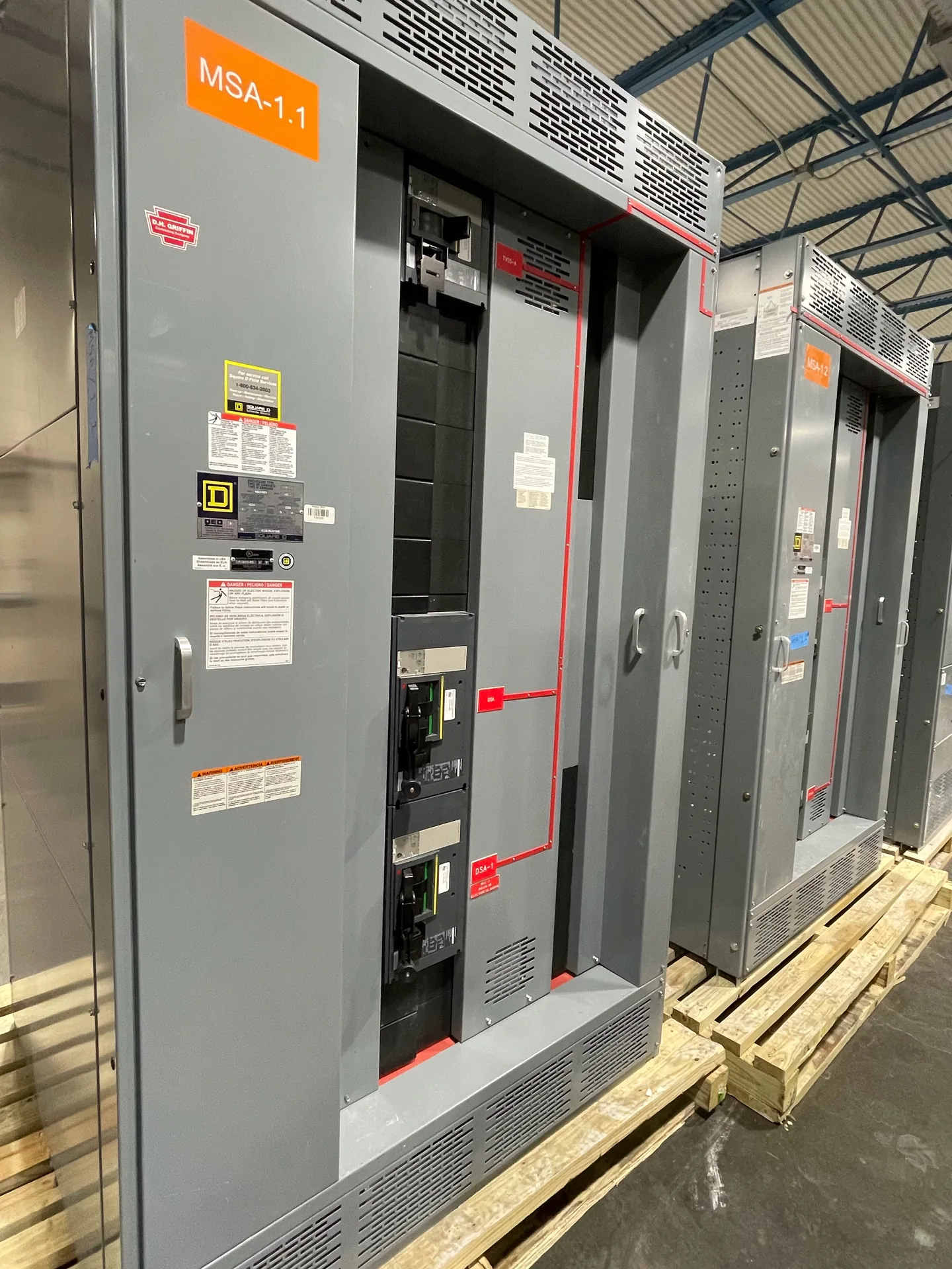
Consider subfeed lugs or breakers, upstream and downstream protection, available space, conductor terminations, and load allocation. A project-specific one-line, load information and physical constraints give the manufacturer a useful basis for discussion. We manufacture and supply new equipment in the United States for projects throughout North Carolina. Ratings and available options must be reviewed against the installation and the required documentation. Discuss your intended schedule and destination when requesting a quotation; lead time and shipping arrangements depend on the final scope.
Panelboard Subfeed Configurations — project planning
Panelboards distribute power to branch circuits and can serve lighting, receptacle or equipment loads when properly selected. A useful schedule identifies system voltage, phase, wire count, main or main-lug configuration, branch circuit quantities and protective device ratings. Review available fault current at the panel location, the assembly rating and the interrupting ratings of installed breakers. Neutral capacity deserves particular attention where load imbalance or harmonics are expected. Reserve space for identified future circuits, and coordinate enclosure mounting, conductor entry, circuit labeling and required access with the installation drawings.
Phase design should begin with the source configuration and the voltage and phase requirements of the connected loads. Distinguish single-phase and three-phase loads, identify any neutral requirements, and provide the engineer with a realistic load schedule. Distribution planning should consider phase balance, nonlinear loads, conductor sizing, grounding, and the effect of motor starting on the system. Where multiple sources or transfer equipment are involved, document the neutral switching and grounding approach for coordinated review. Procurement drawings should communicate phase arrangement and termination requirements clearly to the installation team.
Load Continuity and Switching
Load continuity begins with understanding which services can tolerate an interruption and which require an alternate operating plan. Identify critical loads, available sources, transfer arrangements, and dependencies such as control power and cooling. The design team can then evaluate sectionalizing, protective coordination, and maintenance isolation against the project's operating objectives. Procurement documents should describe the intended switching sequence and any interlocks or monitoring interfaces. Backup equipment and redundant paths still require testing, maintenance, and documented operating procedures; neither should be treated as a guarantee of uninterrupted service.
Busbars distribute power within an assembly and must be designed as part of the complete electrical system. Conductor material, cross section, temperature rise, spacing, insulation, and support arrangement all affect suitability for the intended duty. The design must also account for mechanical forces associated with the specified short-circuit rating. Bending, punching, and routing should follow the approved construction details rather than rules of thumb alone. Phase identification and clear section interfaces help installers connect a lineup correctly while preserving required clearances and access.
Project Location and Shipping
Location affects both switchgear design inputs and the practical work of getting equipment to its installation point. Identify indoor or outdoor placement, environmental exposure, site elevation, seismic design criteria where relevant, and any unusual transportation restrictions. The procurement package should describe delivery access, unloading responsibilities, storage conditions, and the available path through doors or other openings. Discuss shipping splits and field assembly requirements with the project team before finalizing the layout. Protect equipment from moisture and physical damage during transit and storage, following the applicable handling instructions.
Control and metering wiring connects devices such as relays, switches, indicators, and instrument transformers to the functions shown on the project drawings. Conductor size, insulation, terminal selection, and routing should reflect circuit ratings and the installation environment. Labels at both ends make circuits easier to trace during startup and future maintenance. Separation and mechanical support can reduce interference and protect wiring from sharp edges or moving parts. Particular care is needed with current transformer secondary circuits: their connections and test procedures must follow the equipment instructions and applicable safety practices.
Plan Neutral and Grounding Details
Neutral and grounding arrangements affect the equipment design as well as the installation. Identify the system configuration, neutral conductor needs, ground bus, service or feeder application, and any ground-fault protection requirements. The electrical engineer should specify where neutral-to-ground bonding is required and where the neutral must remain isolated, using the adopted code and the actual source configuration. Transformers and generator transfer arrangements can introduce separately derived system questions. Provide these details before drawings are approved, and do not assume that a bonding arrangement suitable at one location is appropriate everywhere downstream.
UL 891 is a safety standard for switchboards; it is not a blanket certification for every product a manufacturer offers. Low-voltage power circuit breaker switchgear is addressed by a different standard, UL 1558, so identify the specified equipment type rather than treating the terms as interchangeable. An individual assembly's certification, voltage, continuous current, and short-circuit ratings depend on its design and applicable certification scope. A manufacturer's UL 891 general coverage program may have limits that differ from those of the standard itself. Request documentation for the specific proposed configuration and its ratings.
Use a Fault Study to Set Ratings
A short-circuit study estimates the fault current available at points throughout the electrical system. The engineer may need utility source data, transformer ratings and impedances, conductor lengths and sizes, motor contributions, and information about generators or other sources. Different operating configurations can produce different results. Provide the study or the project's specified fault-current requirements with the quote request so the proposed assembly and protective devices can be evaluated against the expected duty. Revisit the study when sources, equipment, or system arrangements change; a preliminary figure is not a substitute for the completed engineering review.
A complete inquiry helps the project team compare equipment on the same technical basis. Include a current one-line diagram, load schedule, system voltage and grounding, available fault current, desired protective devices and any coordination requirements. Add site dimensions, access restrictions, cable entry, enclosure exposure and utility requirements. Identify applicable codes and standards, required third-party listing or inspection, submittal drawings and requested test documentation. Reserve future capacity explicitly rather than assuming it is included. A qualified engineer should review the final design, protective settings and installation against the project's actual conditions.
Start with the right specifications
Final capabilities and ratings are confirmed against the application, approved drawings and quotation.
| Project detail | What to provide |
|---|---|
| System | Voltage, phase, wiring and grounding |
| Current | Main and feeder ratings; load information |
| Protection | Available fault current, SCCR and protective device requirements |
| Installation | Enclosure, space, utility requirements and destination |