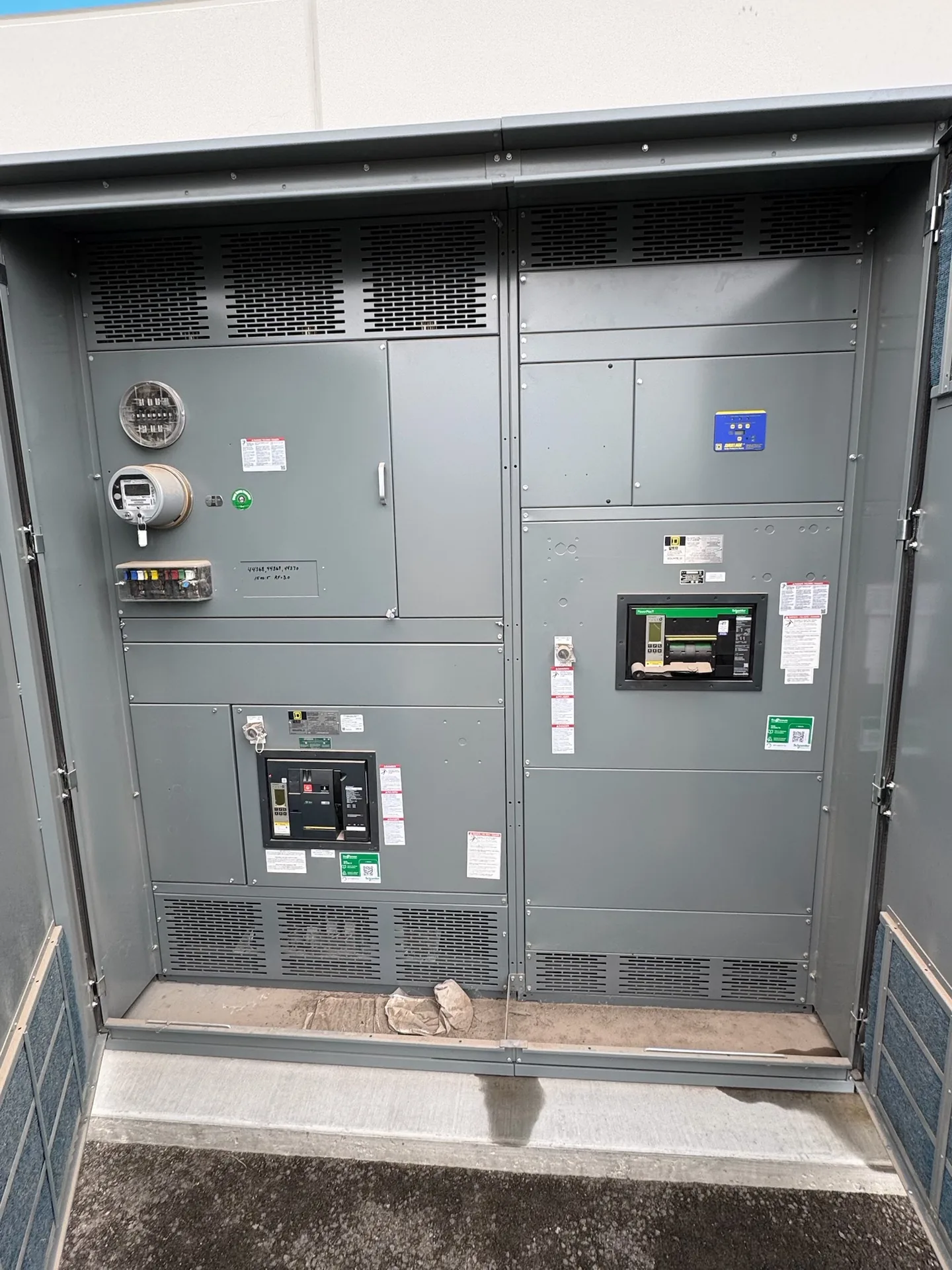
Plan tenant feeder allocation, metering responsibility, access, identification, and future tenant changes. A project-specific one-line, load information and physical constraints give the manufacturer a useful basis for discussion. We manufacture and supply new equipment in the United States for projects throughout North Carolina. Ratings and available options must be reviewed against the installation and the required documentation. Discuss your intended schedule and destination when requesting a quotation; lead time and shipping arrangements depend on the final scope.
Multi Tenant Building Switchgear — project planning
Commercial projects often combine tenant spaces, elevators, lighting, HVAC, and shared building services on a distribution system that may change as occupancy evolves. A useful procurement package identifies the service arrangement, feeder destinations, metering needs, available electrical room space, and provisions for foreseeable tenant changes. The design team should review fault duty and protection coordination across the lineup and downstream equipment. Access for future inspection and replacement deserves attention early, especially when the switchgear must fit through finished corridors, doors, or other restricted routes.
Control and metering wiring connects devices such as relays, switches, indicators, and instrument transformers to the functions shown on the project drawings. Conductor size, insulation, terminal selection, and routing should reflect circuit ratings and the installation environment. Labels at both ends make circuits easier to trace during startup and future maintenance. Separation and mechanical support can reduce interference and protect wiring from sharp edges or moving parts. Particular care is needed with current transformer secondary circuits: their connections and test procedures must follow the equipment instructions and applicable safety practices.
Maintenance Access and Safe Isolation
Switchgear layouts should give qualified personnel a practical way to inspect, test, isolate, and maintain equipment over its service life. Show required working space, door swing, cable access, and the route for removing major components on the project drawings. Identify isolation points and any alternate feeds or control-power sources that could leave parts energized. Procurement specifications can request durable labeling, accessible test provisions, and documentation of operating sequences. Maintenance plans should use site-specific procedures for controlling hazardous energy and verifying absence of voltage before work begins.
Switchgear assembly brings structural sections, protective devices, bus supports, barriers, and control components together according to the approved drawings. Fit matters: door alignment, device mounting, mechanical interlocks, and access to connections affect how the completed equipment can be operated and maintained. Components should be installed within their ratings and in accordance with their instructions and the assembly design. Section joints and removable parts need clear identification for installation. Any design change made during assembly should be reviewed and documented before it becomes part of the final configuration.
Project Drawings and Submittals
Clear drawings help a switchgear supplier and the design team resolve interfaces before equipment is released for fabrication. Include a current one-line diagram, source information, feeder schedule, short-circuit study assumptions when available, and the intended control and metering functions. Physical drawings should identify room dimensions, cable entry, equipment clearances, and relevant obstructions. Request submittals that show lineup arrangement, connection details, device functions, and proposed departures from the specification. Review comments should be reconciled with the engineer of record and other affected trades before fabrication proceeds.
Changes made after delivery, such as adding devices, altering buswork, or drilling an enclosure outside approved locations, can affect equipment ratings or certification. Before work begins, ask the manufacturer whether the proposed modification is permitted and what documentation or approved components are needed. Discuss the plan with the authority having jurisdiction. A qualified field evaluation body may be needed to assess the modified equipment for the specific installation; the authority decides whether to accept it. A field evaluation is not automatic approval and should not be treated as a substitute for a sound design.
Modernization: Designing for Updated Requirements
Modernization can involve supplying a new switchgear or switchboard lineup for a project that needs updated distribution, monitoring, or control functions. The design may incorporate metering, protective relays, communications interfaces, or provisions for future circuits when specified. Each addition needs a defined purpose, power source, wiring interface, and compatibility review. Existing upstream and downstream equipment also influences fault protection and operating sequences. Before the design is finalized, the project team should confirm responsibility for system studies, integration, installation, and acceptance so that new equipment fits the overall plan.
Location affects both switchgear design inputs and the practical work of getting equipment to its installation point. Identify indoor or outdoor placement, environmental exposure, site elevation, seismic design criteria where relevant, and any unusual transportation restrictions. The procurement package should describe delivery access, unloading responsibilities, storage conditions, and the available path through doors or other openings. Discuss shipping splits and field assembly requirements with the project team before finalizing the layout. Protect equipment from moisture and physical damage during transit and storage, following the applicable handling instructions.
Retrofits: New Equipment for an Existing System
A retrofit project may call for new equipment that connects to an existing electrical system while respecting established building constraints. Useful starting information includes current single-line drawings, available fault current, feeder sizes, connection locations, and the physical route into the room. Existing records should be checked against verified site conditions because past modifications may not appear on drawings. The new assembly's ratings and interfaces must be evaluated for the intended installation. Outage sequencing and the boundaries between the new equipment and existing infrastructure should be agreed with the project team.
A commissioning plan should define what is tested, who performs each step, and what evidence is needed for acceptance. Depending on the equipment and project, checks may include device operation, control sequences, metering signals, alarms, and communication with the facility system. Qualified personnel should use procedures appropriate to the equipment and coordinate any energization with the site owner and other responsible parties. Handover documents can include final drawings, test records, equipment instructions, and a list of unresolved items. Actual testing and services depend on the agreed project scope.
Start with the right specifications
Final capabilities and ratings are confirmed against the application, approved drawings and quotation.
| Project detail | What to provide |
|---|---|
| System | Voltage, phase, wiring and grounding |
| Current | Main and feeder ratings; load information |
| Protection | Available fault current, SCCR and protective device requirements |
| Installation | Enclosure, space, utility requirements and destination |