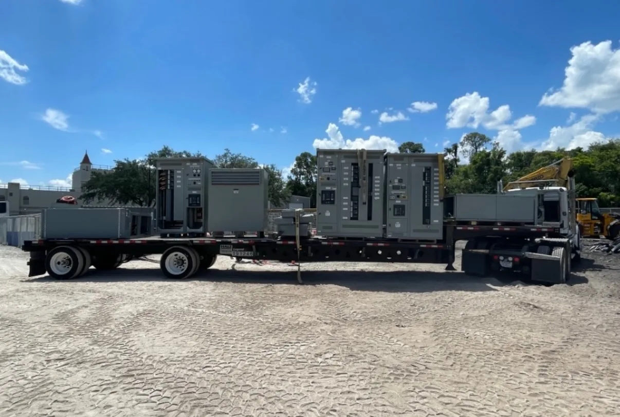
Metal-enclosed switchgear is a family of switchgear assemblies in which the equipment is enclosed by metal. It can contain different switching and protective devices, depending on the design. Metal-clad gear is a more specific category with additional construction requirements; a metal enclosure alone does not establish those features or ratings. The equipment selection should follow the actual source characteristics, connected loads, operating requirements and installation environment. We manufacture new power distribution equipment in the United States and serve customers across North Carolina. Tell us what is known about the one-line, desired configuration and target delivery schedule. A project review establishes the proposed scope and identifies ratings or documentation that need confirmation.
Metal Enclosed Switchgear Glossary Definition — project planning
Metal-clad switchgear is a specific form of metal-enclosed medium-voltage switchgear, not simply any assembly with a metal exterior. IEEE C37.20.2 describes metal-clad construction with drawout electrically operated circuit breakers and grounded metal barriers separating key compartments. For a project, specify the required voltage class, bus current, fault ratings, relay functions and number of feeders. Consider breaker handling, compartment access, control power and maintenance procedures when evaluating the layout. Request confirmation of the applicable standard and the proposed design's construction and ratings; do not assume arc-resistant performance without documented evidence.
Metal-enclosed interrupter switchgear can be considered for medium-voltage distribution where the switching and protection scheme suits the connected loads. A feeder may use a load-interrupter switch and fuses, subject to the selected equipment's ratings and application. Define whether the duty is transformer protection, cable switching or another function, and provide normal load current, fault current and required isolation. Review fuse coordination, visible isolation provisions, interlocks and space for terminations. Metal-enclosed does not automatically mean metal-clad; compare the specified compartmentation and devices against the applicable standard and maintenance plan.
Sheet Metal Fabrication: Enclosures and Access
Sheet metal fabrication turns an equipment layout into the structural and protective enclosure around electrical components. Cutouts, formed panels, mounting surfaces, doors, and covers must align with the intended devices and cable paths. Material selection and finish depend on the specified environment, including indoor or outdoor exposure and corrosion concerns. Edges and openings should be finished to avoid damage to conductors and injury during handling. Enclosure modifications can affect strength, protection, ventilation, or a documented rating, so changes require review against the applicable design and instructions.
A lead-time estimate is more useful when its starting point and milestones are clear. Ask whether the estimate begins at order acceptance, receipt of required commercial information, approval of drawings, or release for production. Break the schedule into engineering, customer review, component procurement, assembly, inspection, and freight. Breakers, metering, special enclosures, and design changes can affect the schedule, as can delayed approvals. Share the required on-site date and any outage or construction constraints. Request an updated schedule when assumptions change, and distinguish an estimate from a confirmed commitment.
Arrange Nationwide Shipping
For projects across the United States, discuss freight requirements before accepting a delivery estimate. Provide the destination, site access restrictions, required delivery window, and whether a loading dock, forklift, or rigging crew is available. Ask how the assembly will be divided and packaged, who arranges unloading, and which freight and insurance terms apply. Confirm any special handling, storage, or weather protection needs with the supplier. On arrival, check the shipment against the packing list and document visible damage on the carrier's paperwork. Report suspected concealed damage promptly under the applicable claim procedures.
Start with suppliers that offer the type of new equipment and voltage class specified for your project. Give each candidate the same one-line, specifications, delivery location, and schedule so their proposals can be compared fairly. Ask about design support, the proposed assembly's ratings and certification, component sourcing, documentation, and warranty process. Request confirmation of the sales channel and the person responsible for changes after order placement. Evaluate technical fit and responsiveness as well as price; a proposal that clearly identifies assumptions and exclusions is easier for your project team to review.
Coordinate Installation Before Delivery
Installation planning starts with the approved equipment dimensions, shipping splits, weights, and manufacturer's handling instructions. Check the route from the unloading point to the electrical room, including doors, elevators, floor loading, rigging access, and the final equipment pad or supports. Coordinate conduit locations, cable bending space, grounding, utility interfaces, and any required shutdown with the responsible trades. Define who will store, assemble, install, test, and commission the equipment. Arrange inspections and any required permits before energization. Early coordination can reveal access or sequencing problems while there is still time to address them.
A short-circuit study estimates the fault current available at points throughout the electrical system. The engineer may need utility source data, transformer ratings and impedances, conductor lengths and sizes, motor contributions, and information about generators or other sources. Different operating configurations can produce different results. Provide the study or the project's specified fault-current requirements with the quote request so the proposed assembly and protective devices can be evaluated against the expected duty. Revisit the study when sources, equipment, or system arrangements change; a preliminary figure is not a substitute for the completed engineering review.
Know What UL 891 Covers
UL 891 is a safety standard for switchboards; it is not a blanket certification for every product a manufacturer offers. Low-voltage power circuit breaker switchgear is addressed by a different standard, UL 1558, so identify the specified equipment type rather than treating the terms as interchangeable. An individual assembly's certification, voltage, continuous current, and short-circuit ratings depend on its design and applicable certification scope. A manufacturer's UL 891 general coverage program may have limits that differ from those of the standard itself. Request documentation for the specific proposed configuration and its ratings.
Neutral and grounding arrangements affect the equipment design as well as the installation. Identify the system configuration, neutral conductor needs, ground bus, service or feeder application, and any ground-fault protection requirements. The electrical engineer should specify where neutral-to-ground bonding is required and where the neutral must remain isolated, using the adopted code and the actual source configuration. Transformers and generator transfer arrangements can introduce separately derived system questions. Provide these details before drawings are approved, and do not assume that a bonding arrangement suitable at one location is appropriate everywhere downstream.
Start with the right specifications
Final capabilities and ratings are confirmed against the application, approved drawings and quotation.
| Project detail | What to provide |
|---|---|
| System | Voltage, phase, wiring and grounding |
| Current | Main and feeder ratings; load information |
| Protection | Available fault current, SCCR and protective device requirements |
| Installation | Enclosure, space, utility requirements and destination |