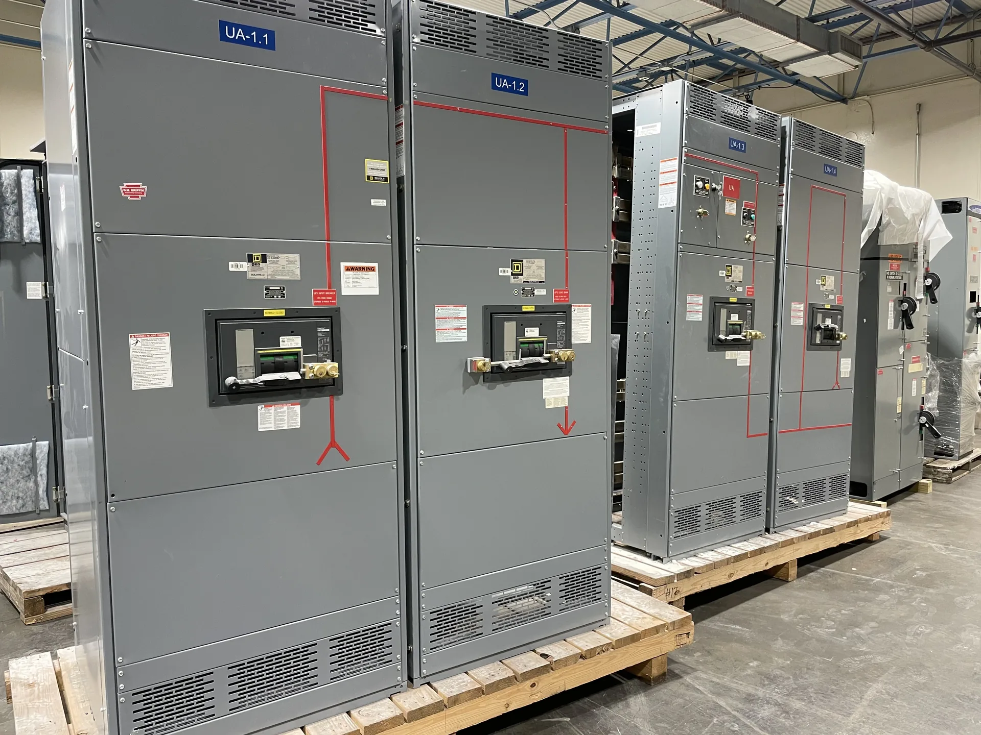
Review separation of primary components, grounded metal barriers where required, cable spaces, bus compartments, and service access. Useful specifications connect the source, protective devices, feeders and physical installation rather than treating each in isolation. Our team builds and supplies new equipment in the USA for North Carolina projects. Provide the information available now, including the intended voltage, current, environment and delivery needs. The engineer of record and the manufacturer can then identify what remains to be clarified before a project-specific quotation.
Metal Clad Switchgear Compartments — project planning
Metal-clad switchgear is a specific form of metal-enclosed medium-voltage switchgear, not simply any assembly with a metal exterior. IEEE C37.20.2 describes metal-clad construction with drawout electrically operated circuit breakers and grounded metal barriers separating key compartments. For a project, specify the required voltage class, bus current, fault ratings, relay functions and number of feeders. Consider breaker handling, compartment access, control power and maintenance procedures when evaluating the layout. Request confirmation of the applicable standard and the proposed design's construction and ratings; do not assume arc-resistant performance without documented evidence.
Sheet metal fabrication turns an equipment layout into the structural and protective enclosure around electrical components. Cutouts, formed panels, mounting surfaces, doors, and covers must align with the intended devices and cable paths. Material selection and finish depend on the specified environment, including indoor or outdoor exposure and corrosion concerns. Edges and openings should be finished to avoid damage to conductors and injury during handling. Enclosure modifications can affect strength, protection, ventilation, or a documented rating, so changes require review against the applicable design and instructions.
Medium-Voltage Metal-Enclosed Interrupter Switchgear
Metal-enclosed interrupter switchgear can be considered for medium-voltage distribution where the switching and protection scheme suits the connected loads. A feeder may use a load-interrupter switch and fuses, subject to the selected equipment's ratings and application. Define whether the duty is transformer protection, cable switching or another function, and provide normal load current, fault current and required isolation. Review fuse coordination, visible isolation provisions, interlocks and space for terminations. Metal-enclosed does not automatically mean metal-clad; compare the specified compartmentation and devices against the applicable standard and maintenance plan.
Service-entrance equipment connects the utility supply to a facility's distribution system and must be coordinated with the utility and the authority having jurisdiction. Establish the service voltage, available fault current, point of connection, metering arrangement, conductor entry and service disconnect configuration early. Specify whether the assembly must be suitable for use as service equipment and verify the proposed markings and documentation. Grounding and neutral bonding must follow the applicable code and the actual service arrangement. Include utility access, required clearances and any restrictions on customer-installed metering or protective devices.
Assembly: Building a Coordinated Equipment Lineup
Switchgear assembly brings structural sections, protective devices, bus supports, barriers, and control components together according to the approved drawings. Fit matters: door alignment, device mounting, mechanical interlocks, and access to connections affect how the completed equipment can be operated and maintained. Components should be installed within their ratings and in accordance with their instructions and the assembly design. Section joints and removable parts need clear identification for installation. Any design change made during assembly should be reviewed and documented before it becomes part of the final configuration.
Switchgear layouts should give qualified personnel a practical way to inspect, test, isolate, and maintain equipment over its service life. Show required working space, door swing, cable access, and the route for removing major components on the project drawings. Identify isolation points and any alternate feeds or control-power sources that could leave parts energized. Procurement specifications can request durable labeling, accessible test provisions, and documentation of operating sequences. Maintenance plans should use site-specific procedures for controlling hazardous energy and verifying absence of voltage before work begins.
Commissioning: Coordinating the Site Interfaces
Commissioning brings the equipment and the wider installation together through a planned sequence of checks before service. The project team should confirm anchorage, accessible clearances, cable terminations, grounding, section splices, and control connections against the drawings and installation instructions. Utility interfaces, protective device settings, and remote signals may require coordination with other parties. Responsibilities for tests, documentation, and energization should be established in advance. Work on electrical equipment must follow applicable safety requirements, including deenergization, lockout or tagging, and verification of the deenergized condition where required.
Enclosure selection starts with the actual location and exposure, not simply an indoor or outdoor label. Specify ambient temperature, altitude, humidity, dust, corrosive agents, water exposure and any washdown or ventilation needs. NEMA Type 1 is generally intended for indoor use, while Type 3R is commonly selected for certain outdoor weather exposures; confirm that the chosen type meets the full site conditions. Account for heaters, drainage, cable entry, working clearances and maintenance access where applicable. An environmental enclosure rating alone does not establish an arc-resistant rating or a specific equipment certification.
Inspection and Testing: Verifying Assembly Details
Inspection provides a structured way to compare an assembled lineup with its approved drawings and component instructions. A review can include device identification, conductor routing, barriers, grounding connections, hardware, labels, and the condition of the enclosure. Mechanical checks may cover door operation, interlocks, and the fit of removable sections where applicable. Findings should be documented and resolved before release. The inspection scope and acceptance criteria belong in the project documentation, because a visual check alone cannot establish every electrical rating or demonstrate performance under fault conditions.
Available fault current is a property of the electrical system at a particular point; interrupting and short-circuit ratings describe equipment capability. Check each breaker or fuse's interrupting rating at the applied voltage against the fault current it may need to interrupt. Separately verify the assembly's short-circuit current or withstand rating and any associated time, device or installation conditions. Include contributions from utility sources, generators and motors as applicable to the study. Series-rated device combinations require documented compatibility and application in accordance with their conditions, not an assumption based on individual ampere ratings.
Start with the right specifications
Final capabilities and ratings are confirmed against the application, approved drawings and quotation.
| Project detail | What to provide |
|---|---|
| System | Voltage, phase, wiring and grounding |
| Current | Main and feeder ratings; load information |
| Protection | Available fault current, SCCR and protective device requirements |
| Installation | Enclosure, space, utility requirements and destination |