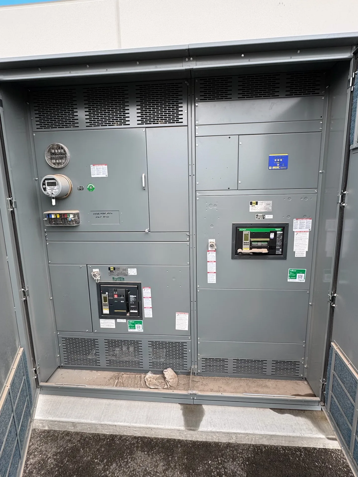
Assess future production capacity, existing bus loading, spare sections, service upgrades, and construction sequencing. A project-specific one-line, load information and physical constraints give the manufacturer a useful basis for discussion. We manufacture and supply new equipment in the United States for projects throughout North Carolina. Ratings and available options must be reviewed against the installation and the required documentation. Discuss your intended schedule and destination when requesting a quotation; lead time and shipping arrangements depend on the final scope.
Manufacturing Plant Electrical Expansion — project planning
Manufacturing distribution planning benefits from a load inventory that separates production machinery, material handling, building services, and planned additions. Identify equipment with sensitive controls or large starting currents, and document how a feeder outage affects the production process. When requesting new switchgear, provide the one-line diagram, feeder schedule, control interfaces, and expectations for metering or spare positions. Review protection settings and sectionalizing options with the electrical engineer so maintenance can be planned around operating needs. Equipment arrangements should leave practical access for inspection and future modifications.
Power plant distribution may serve generating equipment, auxiliary motors, control systems, and other loads that support plant operation. Define normal and alternate sources, operating modes, and the sequence for energizing auxiliaries when preparing a switchgear specification. Protective relaying, interlocks, and control power should be evaluated as an integrated scheme rather than selected independently. Procurement documents should identify interface points with generators, transformers, and supervisory controls, as applicable. Maintenance planning should also address isolation, stored energy, and verification of de-energization before personnel work on equipment.
Retrofits: New Equipment for an Existing System
A retrofit project may call for new equipment that connects to an existing electrical system while respecting established building constraints. Useful starting information includes current single-line drawings, available fault current, feeder sizes, connection locations, and the physical route into the room. Existing records should be checked against verified site conditions because past modifications may not appear on drawings. The new assembly's ratings and interfaces must be evaluated for the intended installation. Outage sequencing and the boundaries between the new equipment and existing infrastructure should be agreed with the project team.
Service-entrance equipment connects the utility supply to a facility's distribution system and must be coordinated with the utility and the authority having jurisdiction. Establish the service voltage, available fault current, point of connection, metering arrangement, conductor entry and service disconnect configuration early. Specify whether the assembly must be suitable for use as service equipment and verify the proposed markings and documentation. Grounding and neutral bonding must follow the applicable code and the actual service arrangement. Include utility access, required clearances and any restrictions on customer-installed metering or protective devices.
Discuss Lead Time Before Ordering
A lead-time estimate is more useful when its starting point and milestones are clear. Ask whether the estimate begins at order acceptance, receipt of required commercial information, approval of drawings, or release for production. Break the schedule into engineering, customer review, component procurement, assembly, inspection, and freight. Breakers, metering, special enclosures, and design changes can affect the schedule, as can delayed approvals. Share the required on-site date and any outage or construction constraints. Request an updated schedule when assumptions change, and distinguish an estimate from a confirmed commitment.
Phase design should begin with the source configuration and the voltage and phase requirements of the connected loads. Distinguish single-phase and three-phase loads, identify any neutral requirements, and provide the engineer with a realistic load schedule. Distribution planning should consider phase balance, nonlinear loads, conductor sizing, grounding, and the effect of motor starting on the system. Where multiple sources or transfer equipment are involved, document the neutral switching and grounding approach for coordinated review. Procurement drawings should communicate phase arrangement and termination requirements clearly to the installation team.
Busbar Work: Preparing Reliable Joints
A busbar joint depends on compatible materials, prepared contact surfaces, specified hardware, and the correct installation method. Surface treatment and joint compounds, when required, should follow the assembly and component instructions rather than a generic recipe. Fasteners should be tightened to the specified torque using suitable tools, with access provided for inspection and maintenance. The same care applies to field-installed splice connections between shipping sections. Unapproved drilling, substitution, or rework can affect current carrying capacity, clearances, or short-circuit performance and should be reviewed before proceeding.
A useful switchgear design starts with the electrical system, not the enclosure dimensions alone. The project team establishes nominal voltage, frequency, phase configuration, grounding method, expected loads, and available fault current at the installation point. These inputs guide equipment ratings, protective device selection, and the arrangement of incoming and outgoing circuits. Future feeders or alternate sources should be identified early because they can affect bus capacity and layout. The final design must also reflect the applicable codes, the site conditions, and the ratings of the complete assembly.
Modernization: Designing for Updated Requirements
Modernization can involve supplying a new switchgear or switchboard lineup for a project that needs updated distribution, monitoring, or control functions. The design may incorporate metering, protective relays, communications interfaces, or provisions for future circuits when specified. Each addition needs a defined purpose, power source, wiring interface, and compatibility review. Existing upstream and downstream equipment also influences fault protection and operating sequences. Before the design is finalized, the project team should confirm responsibility for system studies, integration, installation, and acceptance so that new equipment fits the overall plan.
Clear drawings help a switchgear supplier and the design team resolve interfaces before equipment is released for fabrication. Include a current one-line diagram, source information, feeder schedule, short-circuit study assumptions when available, and the intended control and metering functions. Physical drawings should identify room dimensions, cable entry, equipment clearances, and relevant obstructions. Request submittals that show lineup arrangement, connection details, device functions, and proposed departures from the specification. Review comments should be reconciled with the engineer of record and other affected trades before fabrication proceeds.
Start with the right specifications
Final capabilities and ratings are confirmed against the application, approved drawings and quotation.
| Project detail | What to provide |
|---|---|
| System | Voltage, phase, wiring and grounding |
| Current | Main and feeder ratings; load information |
| Protection | Available fault current, SCCR and protective device requirements |
| Installation | Enclosure, space, utility requirements and destination |