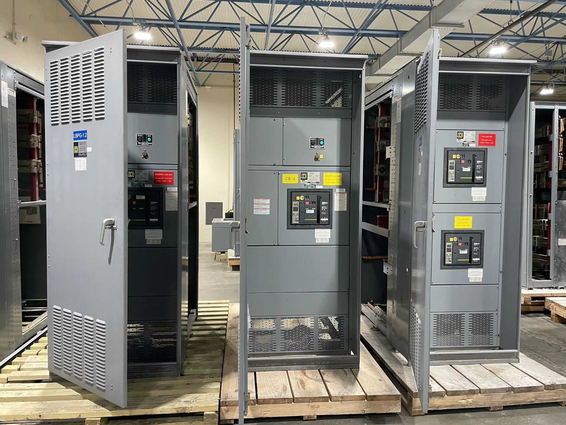
Plan manufacturing facilities power distribution for a project in Raleigh, North Carolina, focusing on production lines, motor control, process expansion, load monitoring, and staged installation. Confirm the serving utility, permit authority, and requirements for occupied-site upgrades. Confirm site-specific loads, the serving utility, local approvals, and equipment scope rather than assuming local availability. The starting point is the actual electrical system and how the lineup will be installed and operated. We build and supply new power distribution equipment in the United States for North Carolina projects. Share the intended ratings, application, available space and schedule with our team so they can be evaluated against the proposed scope. The final configuration, availability and delivery details are established in the project quotation.
Manufacturing Facilities Switchgear in Raleigh NC — project planning
A motor control center groups motor starters and related control equipment so multiple motors can be operated and protected from an organized lineup. Provide a motor schedule with horsepower, voltage, full-load current, starting method and duty for each load. Specify disconnects, overload protection, starter type, control voltage and any variable-frequency drives or communication interfaces. Review heat dissipation, available fault current, feeder sizing and space for future units. Drawout construction, network features and spare compartments should be confirmed for the proposed design rather than assumed from the term MCC.
Manufacturing distribution planning benefits from a load inventory that separates production machinery, material handling, building services, and planned additions. Identify equipment with sensitive controls or large starting currents, and document how a feeder outage affects the production process. When requesting new switchgear, provide the one-line diagram, feeder schedule, control interfaces, and expectations for metering or spare positions. Review protection settings and sectionalizing options with the electrical engineer so maintenance can be planned around operating needs. Equipment arrangements should leave practical access for inspection and future modifications.
Phase Design and Load Balance
Phase design should begin with the source configuration and the voltage and phase requirements of the connected loads. Distinguish single-phase and three-phase loads, identify any neutral requirements, and provide the engineer with a realistic load schedule. Distribution planning should consider phase balance, nonlinear loads, conductor sizing, grounding, and the effect of motor starting on the system. Where multiple sources or transfer equipment are involved, document the neutral switching and grounding approach for coordinated review. Procurement drawings should communicate phase arrangement and termination requirements clearly to the installation team.
Load continuity begins with understanding which services can tolerate an interruption and which require an alternate operating plan. Identify critical loads, available sources, transfer arrangements, and dependencies such as control power and cooling. The design team can then evaluate sectionalizing, protective coordination, and maintenance isolation against the project's operating objectives. Procurement documents should describe the intended switching sequence and any interlocks or monitoring interfaces. Backup equipment and redundant paths still require testing, maintenance, and documented operating procedures; neither should be treated as a guarantee of uninterrupted service.
Maintenance Access and Safe Isolation
Switchgear layouts should give qualified personnel a practical way to inspect, test, isolate, and maintain equipment over its service life. Show required working space, door swing, cable access, and the route for removing major components on the project drawings. Identify isolation points and any alternate feeds or control-power sources that could leave parts energized. Procurement specifications can request durable labeling, accessible test provisions, and documentation of operating sequences. Maintenance plans should use site-specific procedures for controlling hazardous energy and verifying absence of voltage before work begins.
Commissioning brings the equipment and the wider installation together through a planned sequence of checks before service. The project team should confirm anchorage, accessible clearances, cable terminations, grounding, section splices, and control connections against the drawings and installation instructions. Utility interfaces, protective device settings, and remote signals may require coordination with other parties. Responsibilities for tests, documentation, and energization should be established in advance. Work on electrical equipment must follow applicable safety requirements, including deenergization, lockout or tagging, and verification of the deenergized condition where required.
Plan Neutral and Grounding Details
Neutral and grounding arrangements affect the equipment design as well as the installation. Identify the system configuration, neutral conductor needs, ground bus, service or feeder application, and any ground-fault protection requirements. The electrical engineer should specify where neutral-to-ground bonding is required and where the neutral must remain isolated, using the adopted code and the actual source configuration. Transformers and generator transfer arrangements can introduce separately derived system questions. Provide these details before drawings are approved, and do not assume that a bonding arrangement suitable at one location is appropriate everywhere downstream.
A complete inquiry helps the project team compare equipment on the same technical basis. Include a current one-line diagram, load schedule, system voltage and grounding, available fault current, desired protective devices and any coordination requirements. Add site dimensions, access restrictions, cable entry, enclosure exposure and utility requirements. Identify applicable codes and standards, required third-party listing or inspection, submittal drawings and requested test documentation. Reserve future capacity explicitly rather than assuming it is included. A qualified engineer should review the final design, protective settings and installation against the project's actual conditions.
UL 891: Understanding Switchboard Requirements
UL 891 is a standard for dead-front switchboards rated 1,000 volts or less. It is not the standard used to establish requirements for switchgear rated above 1,000 volts; that equipment requires consideration of other applicable standards and ratings. For a switchboard project, the specified voltage, continuous current, short-circuit current rating, and intended service conditions must match the application. A UL 891 listing must not be assumed from the use of listed components or the mention of the standard. Verify any claimed listing for the actual assembly using its markings and certification documentation.
Control and metering wiring connects devices such as relays, switches, indicators, and instrument transformers to the functions shown on the project drawings. Conductor size, insulation, terminal selection, and routing should reflect circuit ratings and the installation environment. Labels at both ends make circuits easier to trace during startup and future maintenance. Separation and mechanical support can reduce interference and protect wiring from sharp edges or moving parts. Particular care is needed with current transformer secondary circuits: their connections and test procedures must follow the equipment instructions and applicable safety practices.
Start with the right specifications
Final capabilities and ratings are confirmed against the application, approved drawings and quotation.
| Project detail | What to provide |
|---|---|
| System | Voltage, phase, wiring and grounding |
| Current | Main and feeder ratings; load information |
| Protection | Available fault current, SCCR and protective device requirements |
| Installation | Enclosure, space, utility requirements and destination |