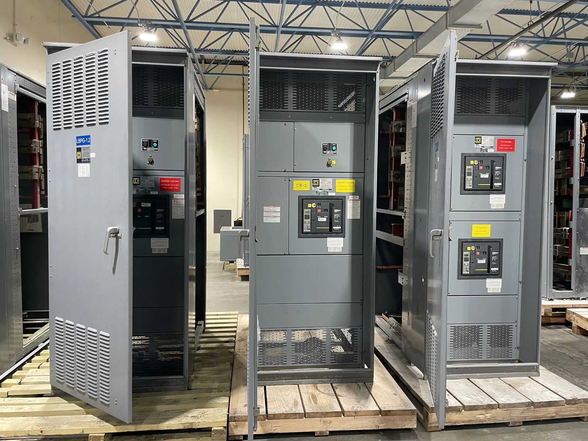
Consider main-lug configurations, upstream disconnect and protection interfaces, feeder sizing, and use within the system design. A clear request gives the manufacturer a way to assess electrical ratings, physical fit, operating needs and delivery together. We build and supply new equipment in the USA for projects across North Carolina. Begin with the information you have, then identify outstanding items with the design team. Specifications, listing requirements, project timing and shipping are confirmed as part of the quotation and engineering review.
Main Lug Panelboards — project planning
A switchboard can organize a main disconnect and feeder protective devices in a floor-mounted distribution assembly. Define the number and size of feeders, metering needs, cable entry direction and required working clearances before selecting a layout. Depending on the design, molded-case, insulated-case or other suitable protective devices may be considered. UL 891 addresses switchboards rated no more than 1,000 V; it is not a medium- or high-voltage switchgear standard. Request the proposed assembly's voltage, continuous current and short-circuit ratings, along with any listing evidence required for the project.
Panelboards distribute power to branch circuits and can serve lighting, receptacle or equipment loads when properly selected. A useful schedule identifies system voltage, phase, wire count, main or main-lug configuration, branch circuit quantities and protective device ratings. Review available fault current at the panel location, the assembly rating and the interrupting ratings of installed breakers. Neutral capacity deserves particular attention where load imbalance or harmonics are expected. Reserve space for identified future circuits, and coordinate enclosure mounting, conductor entry, circuit labeling and required access with the installation drawings.
Phase Design and Load Balance
Phase design should begin with the source configuration and the voltage and phase requirements of the connected loads. Distinguish single-phase and three-phase loads, identify any neutral requirements, and provide the engineer with a realistic load schedule. Distribution planning should consider phase balance, nonlinear loads, conductor sizing, grounding, and the effect of motor starting on the system. Where multiple sources or transfer equipment are involved, document the neutral switching and grounding approach for coordinated review. Procurement drawings should communicate phase arrangement and termination requirements clearly to the installation team.
A useful switchgear design starts with the electrical system, not the enclosure dimensions alone. The project team establishes nominal voltage, frequency, phase configuration, grounding method, expected loads, and available fault current at the installation point. These inputs guide equipment ratings, protective device selection, and the arrangement of incoming and outgoing circuits. Future feeders or alternate sources should be identified early because they can affect bus capacity and layout. The final design must also reflect the applicable codes, the site conditions, and the ratings of the complete assembly.
Custom Design: Planning the Physical Layout
A project-specific equipment layout connects electrical requirements to the space available for installation and maintenance. Section dimensions, cable entry, conductor bending space, ventilation, and access to operating devices all influence the arrangement. The design should account for doors, removable covers, lifting provisions, and the working clearances required at the installed location. Coordination with the building team helps identify obstructions, floor loading, and the route into the electrical room. A documented layout also makes it easier to review future expansion without assuming unused space is automatically suitable for additional equipment.
Engineering review compares the proposed equipment with the project's electrical and physical requirements before construction proceeds. The review can address single-line diagrams, device ratings, available fault current, grounding, control interfaces, enclosure selection, and installation constraints. Protective device settings and coordination depend on the broader power system and may require separate studies by the responsible design professional. Drawing revisions and equipment substitutions should be tracked so all parties work from the same information. Approval of a drawing alone does not replace required product evaluation, inspection, or authority approval.
Interrupting and Short-Circuit Ratings
Available fault current is a property of the electrical system at a particular point; interrupting and short-circuit ratings describe equipment capability. Check each breaker or fuse's interrupting rating at the applied voltage against the fault current it may need to interrupt. Separately verify the assembly's short-circuit current or withstand rating and any associated time, device or installation conditions. Include contributions from utility sources, generators and motors as applicable to the study. Series-rated device combinations require documented compatibility and application in accordance with their conditions, not an assumption based on individual ampere ratings.
Utility-facing switchgear projects require early coordination over the boundary between the utility system and customer-owned distribution. The procurement package should identify the point of connection, incoming source characteristics, metering arrangements, protection responsibilities, and the information needed for the utility's review. Show current and voltage transformer locations where applicable, along with communication and control interfaces. Confirm assumptions about available fault current and future system changes with the responsible parties. Clear ownership and operating responsibilities help avoid gaps when equipment is commissioned, switched, or maintained.
Project Drawings and Submittals
Clear drawings help a switchgear supplier and the design team resolve interfaces before equipment is released for fabrication. Include a current one-line diagram, source information, feeder schedule, short-circuit study assumptions when available, and the intended control and metering functions. Physical drawings should identify room dimensions, cable entry, equipment clearances, and relevant obstructions. Request submittals that show lineup arrangement, connection details, device functions, and proposed departures from the specification. Review comments should be reconciled with the engineer of record and other affected trades before fabrication proceeds.
A manufacturer designs or assembles new equipment to an agreed configuration and can explain construction, engineering details, and applicable product documentation. A distributor may help customers select and purchase equipment, coordinate orders, and provide a local point of contact. The exact division of work depends on the project and sales channel. Ask who owns the quote, answers technical questions, manages revisions, handles warranty requests, and coordinates delivery. Whether you purchase directly or through a distributor, confirm the named manufacturer and the equipment configuration in the proposal before placing an order.
Start with the right specifications
Final capabilities and ratings are confirmed against the application, approved drawings and quotation.
| Project detail | What to provide |
|---|---|
| System | Voltage, phase, wiring and grounding |
| Current | Main and feeder ratings; load information |
| Protection | Available fault current, SCCR and protective device requirements |
| Installation | Enclosure, space, utility requirements and destination |