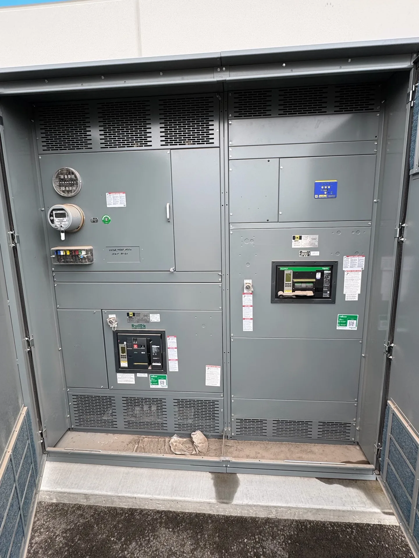
Consider duty cycle, demand, voltage variation, feeder sizing, and power-quality study for welding equipment. A clear request gives the manufacturer a way to assess electrical ratings, physical fit, operating needs and delivery together. We build and supply new equipment in the USA for projects across North Carolina. Begin with the information you have, then identify outstanding items with the design team. Specifications, listing requirements, project timing and shipping are confirmed as part of the quotation and engineering review.
Industrial Welding Load Distribution — project planning
Phase design should begin with the source configuration and the voltage and phase requirements of the connected loads. Distinguish single-phase and three-phase loads, identify any neutral requirements, and provide the engineer with a realistic load schedule. Distribution planning should consider phase balance, nonlinear loads, conductor sizing, grounding, and the effect of motor starting on the system. Where multiple sources or transfer equipment are involved, document the neutral switching and grounding approach for coordinated review. Procurement drawings should communicate phase arrangement and termination requirements clearly to the installation team.
Industrial switchgear selections should reflect the operating environment as well as the electrical load. Document large motors, variable frequency drives, process heaters, and other equipment that can affect starting, harmonics, or protective settings. Identify dust, moisture, temperature, vibration, and corrosive conditions that may influence enclosure and installation choices. Procurement drawings should show source connections, feeder functions, grounding, and available working space. A coordinated review of isolation points and protective devices helps maintenance personnel plan work without assuming that a disconnected machine is free of every energy source.
Load Continuity and Switching
Load continuity begins with understanding which services can tolerate an interruption and which require an alternate operating plan. Identify critical loads, available sources, transfer arrangements, and dependencies such as control power and cooling. The design team can then evaluate sectionalizing, protective coordination, and maintenance isolation against the project's operating objectives. Procurement documents should describe the intended switching sequence and any interlocks or monitoring interfaces. Backup equipment and redundant paths still require testing, maintenance, and documented operating procedures; neither should be treated as a guarantee of uninterrupted service.
A short-circuit study estimates the fault current available at points throughout the electrical system. The engineer may need utility source data, transformer ratings and impedances, conductor lengths and sizes, motor contributions, and information about generators or other sources. Different operating configurations can produce different results. Provide the study or the project's specified fault-current requirements with the quote request so the proposed assembly and protective devices can be evaluated against the expected duty. Revisit the study when sources, equipment, or system arrangements change; a preliminary figure is not a substitute for the completed engineering review.
Inspection and Testing: Electrical Verification
Electrical verification is selected for the equipment and the project rather than assumed from a generic checklist. Depending on the design, procedures may include continuity checks, control circuit functional tests, and insulation resistance testing where appropriate. Test voltages, temporary disconnections, and sensitive electronic components must be addressed in the written procedure and equipment instructions. Results should be recorded with the applicable acceptance criteria and any corrective action. Routine production or field tests should not be represented as substitutes for the design evaluation or short-circuit testing needed to support an equipment rating.
A project-specific equipment layout connects electrical requirements to the space available for installation and maintenance. Section dimensions, cable entry, conductor bending space, ventilation, and access to operating devices all influence the arrangement. The design should account for doors, removable covers, lifting provisions, and the working clearances required at the installed location. Coordination with the building team helps identify obstructions, floor loading, and the route into the electrical room. A documented layout also makes it easier to review future expansion without assuming unused space is automatically suitable for additional equipment.
Maintenance Access and Safe Isolation
Switchgear layouts should give qualified personnel a practical way to inspect, test, isolate, and maintain equipment over its service life. Show required working space, door swing, cable access, and the route for removing major components on the project drawings. Identify isolation points and any alternate feeds or control-power sources that could leave parts energized. Procurement specifications can request durable labeling, accessible test provisions, and documentation of operating sequences. Maintenance plans should use site-specific procedures for controlling hazardous energy and verifying absence of voltage before work begins.
Short-circuit current rating, or SCCR, describes the fault current an assembly or component can withstand under specified conditions at a stated voltage. A breaker's or fuse's interrupting rating describes the fault current that device can safely interrupt under specified conditions. Both must be considered against the available fault current at the installation point; a high breaker rating alone does not establish the assembly rating. A qualified designer should also review any conditions attached to the equipment rating. Series-rated combinations require specific permitted device combinations and application checks, not an assumption based on the upstream breaker alone.
Understand Switchgear Pricing Inputs
The price of new distribution equipment depends on its electrical ratings, physical construction, and included components. Main and feeder device types, bus material and capacity, short-circuit requirements, enclosure rating, metering, controls, and spare provisions can all affect the proposal. Engineering, testing, special documentation, freight, and site services may be included or quoted separately. Provide comparable specifications to each supplier and review exclusions, alternates, and payment terms alongside the base price. If the design is incomplete, ask which assumptions are driving the estimate and what could change when the drawings are finalized.
Switchgear can expose workers to shock and arc-flash hazards even after a disconnect has been opened. Installation, testing, operation, and maintenance should be assigned to personnel qualified for the task and the equipment involved. Follow applicable OSHA requirements, the employer's safety procedures, and the equipment instructions. Establish an electrically safe work condition where required: identify all sources, de-energize, apply the required lockout and tagging procedures, and have a qualified person verify absence of voltage. Address stored energy and possible backfeeds. Energized work requires appropriate justification and protective measures under applicable rules.
Start with the right specifications
Final capabilities and ratings are confirmed against the application, approved drawings and quotation.
| Project detail | What to provide |
|---|---|
| System | Voltage, phase, wiring and grounding |
| Current | Main and feeder ratings; load information |
| Protection | Available fault current, SCCR and protective device requirements |
| Installation | Enclosure, space, utility requirements and destination |