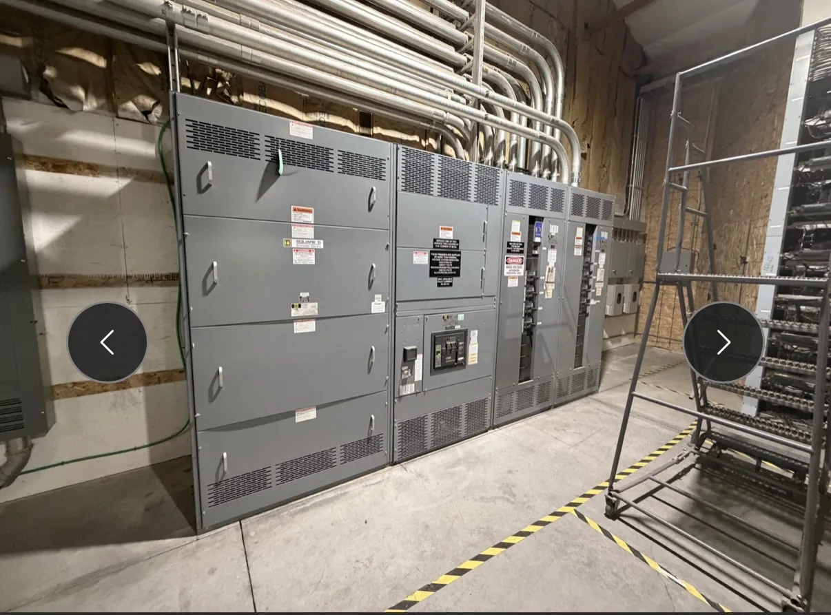
An automatic transfer switch monitors its power sources and, when programmed conditions are met, transfers the connected load from one source to another. It can return the load when the preferred source is acceptable again. Transfer timing, generator signals, transition type, and interlocking depend on the equipment and project requirements. Useful specifications connect the source, protective devices, feeders and physical installation rather than treating each in isolation. Our team builds and supplies new equipment in the USA for North Carolina projects. Provide the information available now, including the intended voltage, current, environment and delivery needs. The engineer of record and the manufacturer can then identify what remains to be clarified before a project-specific quotation.
How Does an Automatic Transfer Switch Work — project planning
An automatic transfer switch selects between normal and alternate sources according to the project's transfer sequence. Define source voltages, phase rotation, load current, generator starting signals, retransfer settings and whether open-transition or another transfer method is needed. The engineer should determine whether the neutral is switched based on the grounding arrangement and applicable requirements. Check the switch's withstand and closing rating against available fault current from each source, the specified upstream protection and applicable time limitations. Identify any service-entrance use and request documentation for the specified equipment standard, such as UL 1008.
Modernization can involve supplying a new switchgear or switchboard lineup for a project that needs updated distribution, monitoring, or control functions. The design may incorporate metering, protective relays, communications interfaces, or provisions for future circuits when specified. Each addition needs a defined purpose, power source, wiring interface, and compatibility review. Existing upstream and downstream equipment also influences fault protection and operating sequences. Before the design is finalized, the project team should confirm responsibility for system studies, integration, installation, and acceptance so that new equipment fits the overall plan.
UL 891: Understanding Switchboard Requirements
UL 891 is a standard for dead-front switchboards rated 1,000 volts or less. It is not the standard used to establish requirements for switchgear rated above 1,000 volts; that equipment requires consideration of other applicable standards and ratings. For a switchboard project, the specified voltage, continuous current, short-circuit current rating, and intended service conditions must match the application. A UL 891 listing must not be assumed from the use of listed components or the mention of the standard. Verify any claimed listing for the actual assembly using its markings and certification documentation.
Neutral and grounding arrangements affect the equipment design as well as the installation. Identify the system configuration, neutral conductor needs, ground bus, service or feeder application, and any ground-fault protection requirements. The electrical engineer should specify where neutral-to-ground bonding is required and where the neutral must remain isolated, using the adopted code and the actual source configuration. Transformers and generator transfer arrangements can introduce separately derived system questions. Provide these details before drawings are approved, and do not assume that a bonding arrangement suitable at one location is appropriate everywhere downstream.
Know What UL 891 Covers
UL 891 is a safety standard for switchboards; it is not a blanket certification for every product a manufacturer offers. Low-voltage power circuit breaker switchgear is addressed by a different standard, UL 1558, so identify the specified equipment type rather than treating the terms as interchangeable. An individual assembly's certification, voltage, continuous current, and short-circuit ratings depend on its design and applicable certification scope. A manufacturer's UL 891 general coverage program may have limits that differ from those of the standard itself. Request documentation for the specific proposed configuration and its ratings.
Before selecting equipment dimensions, check the electrical room for the working space and access needed around the proposed assembly. Required clearance depends on the applicable code, voltage, equipment arrangement, and conditions at the installation. Door swing, rear access when needed, ventilation, equipment removal, and entry or egress also affect the layout. Compare the manufacturer's drawings with architectural and mechanical plans, including nearby piping and other obstructions. The engineer and authority having jurisdiction should confirm applicable requirements, and the completed working space must remain unobstructed rather than becoming storage.
Busbar Work: Preparing Reliable Joints
A busbar joint depends on compatible materials, prepared contact surfaces, specified hardware, and the correct installation method. Surface treatment and joint compounds, when required, should follow the assembly and component instructions rather than a generic recipe. Fasteners should be tightened to the specified torque using suitable tools, with access provided for inspection and maintenance. The same care applies to field-installed splice connections between shipping sections. Unapproved drilling, substitution, or rework can affect current carrying capacity, clearances, or short-circuit performance and should be reviewed before proceeding.
The price of new distribution equipment depends on its electrical ratings, physical construction, and included components. Main and feeder device types, bus material and capacity, short-circuit requirements, enclosure rating, metering, controls, and spare provisions can all affect the proposal. Engineering, testing, special documentation, freight, and site services may be included or quoted separately. Provide comparable specifications to each supplier and review exclusions, alternates, and payment terms alongside the base price. If the design is incomplete, ask which assumptions are driving the estimate and what could change when the drawings are finalized.
Manage the Submittal Process
A submittal package gives the design and construction teams an opportunity to check the proposed equipment against the project documents. Depending on the contract, it may include drawings, device data sheets, ratings, enclosure details, metering information, and certification documentation. Agree on the required contents and the review sequence before ordering. The engineer, contractor, owner, and utility may each need to review different items. Consolidate comments, track revisions, and return a clear disposition to the supplier. Submittal review does not replace the separate inspections and approvals required for installation.
Protection coordination considers how upstream and downstream devices respond to faults and overloads. The goal is often to isolate the affected circuit while keeping as much of the remaining system in service as practical. Where selective coordination is required, the engineer must evaluate the applicable devices across the required range of currents and operating times. Time-current curves, manufacturer coordination tables, available fault current, and actual trip settings may all matter. Share continuity requirements and relevant system information early; a high equipment rating or adjustable trip unit does not by itself prove selective coordination.
Start with the right specifications
Final capabilities and ratings are confirmed against the application, approved drawings and quotation.
| Project detail | What to provide |
|---|---|
| System | Voltage, phase, wiring and grounding |
| Current | Main and feeder ratings; load information |
| Protection | Available fault current, SCCR and protective device requirements |
| Installation | Enclosure, space, utility requirements and destination |