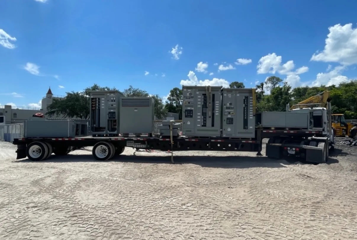
Identify critical care load interfaces, transfer requirements, protective coordination, and documented interruption limits. A project-specific one-line, load information and physical constraints give the manufacturer a useful basis for discussion. We manufacture and supply new equipment in the United States for projects throughout North Carolina. Ratings and available options must be reviewed against the installation and the required documentation. Discuss your intended schedule and destination when requesting a quotation; lead time and shipping arrangements depend on the final scope.
Hospital Critical Care Power Distribution — project planning
Load continuity begins with understanding which services can tolerate an interruption and which require an alternate operating plan. Identify critical loads, available sources, transfer arrangements, and dependencies such as control power and cooling. The design team can then evaluate sectionalizing, protective coordination, and maintenance isolation against the project's operating objectives. Procurement documents should describe the intended switching sequence and any interlocks or monitoring interfaces. Backup equipment and redundant paths still require testing, maintenance, and documented operating procedures; neither should be treated as a guarantee of uninterrupted service.
Hospital distribution planning must account for clinical spaces, essential support equipment, and the differing consequences of an interruption. Define which loads need alternate sources, how transfer equipment interfaces with the switchgear, and where maintenance isolation is needed. Procurement should include one-line diagrams, protective device preferences, and the intended sequence of operation for normal and emergency sources. Coordinate planned work with the facility's clinical and engineering teams, and establish a safe switching procedure rather than assuming that a redundant source eliminates every outage or electrical hazard.
Phase Design and Load Balance
Phase design should begin with the source configuration and the voltage and phase requirements of the connected loads. Distinguish single-phase and three-phase loads, identify any neutral requirements, and provide the engineer with a realistic load schedule. Distribution planning should consider phase balance, nonlinear loads, conductor sizing, grounding, and the effect of motor starting on the system. Where multiple sources or transfer equipment are involved, document the neutral switching and grounding approach for coordinated review. Procurement drawings should communicate phase arrangement and termination requirements clearly to the installation team.
Utility-facing switchgear projects require early coordination over the boundary between the utility system and customer-owned distribution. The procurement package should identify the point of connection, incoming source characteristics, metering arrangements, protection responsibilities, and the information needed for the utility's review. Show current and voltage transformer locations where applicable, along with communication and control interfaces. Confirm assumptions about available fault current and future system changes with the responsible parties. Clear ownership and operating responsibilities help avoid gaps when equipment is commissioned, switched, or maintained.
Assembly: Building a Coordinated Equipment Lineup
Switchgear assembly brings structural sections, protective devices, bus supports, barriers, and control components together according to the approved drawings. Fit matters: door alignment, device mounting, mechanical interlocks, and access to connections affect how the completed equipment can be operated and maintained. Components should be installed within their ratings and in accordance with their instructions and the assembly design. Section joints and removable parts need clear identification for installation. Any design change made during assembly should be reviewed and documented before it becomes part of the final configuration.
Engineering review compares the proposed equipment with the project's electrical and physical requirements before construction proceeds. The review can address single-line diagrams, device ratings, available fault current, grounding, control interfaces, enclosure selection, and installation constraints. Protective device settings and coordination depend on the broader power system and may require separate studies by the responsible design professional. Drawing revisions and equipment substitutions should be tracked so all parties work from the same information. Approval of a drawing alone does not replace required product evaluation, inspection, or authority approval.
Coordinate Protective Devices
Protection coordination considers how upstream and downstream devices respond to faults and overloads. The goal is often to isolate the affected circuit while keeping as much of the remaining system in service as practical. Where selective coordination is required, the engineer must evaluate the applicable devices across the required range of currents and operating times. Time-current curves, manufacturer coordination tables, available fault current, and actual trip settings may all matter. Share continuity requirements and relevant system information early; a high equipment rating or adjustable trip unit does not by itself prove selective coordination.
Installation planning starts with the approved equipment dimensions, shipping splits, weights, and manufacturer's handling instructions. Check the route from the unloading point to the electrical room, including doors, elevators, floor loading, rigging access, and the final equipment pad or supports. Coordinate conduit locations, cable bending space, grounding, utility interfaces, and any required shutdown with the responsible trades. Define who will store, assemble, install, test, and commission the equipment. Arrange inspections and any required permits before energization. Early coordination can reveal access or sequencing problems while there is still time to address them.
Project Drawings and Submittals
Clear drawings help a switchgear supplier and the design team resolve interfaces before equipment is released for fabrication. Include a current one-line diagram, source information, feeder schedule, short-circuit study assumptions when available, and the intended control and metering functions. Physical drawings should identify room dimensions, cable entry, equipment clearances, and relevant obstructions. Request submittals that show lineup arrangement, connection details, device functions, and proposed departures from the specification. Review comments should be reconciled with the engineer of record and other affected trades before fabrication proceeds.
Location affects both switchgear design inputs and the practical work of getting equipment to its installation point. Identify indoor or outdoor placement, environmental exposure, site elevation, seismic design criteria where relevant, and any unusual transportation restrictions. The procurement package should describe delivery access, unloading responsibilities, storage conditions, and the available path through doors or other openings. Discuss shipping splits and field assembly requirements with the project team before finalizing the layout. Protect equipment from moisture and physical damage during transit and storage, following the applicable handling instructions.
Start with the right specifications
Final capabilities and ratings are confirmed against the application, approved drawings and quotation.
| Project detail | What to provide |
|---|---|
| System | Voltage, phase, wiring and grounding |
| Current | Main and feeder ratings; load information |
| Protection | Available fault current, SCCR and protective device requirements |
| Installation | Enclosure, space, utility requirements and destination |