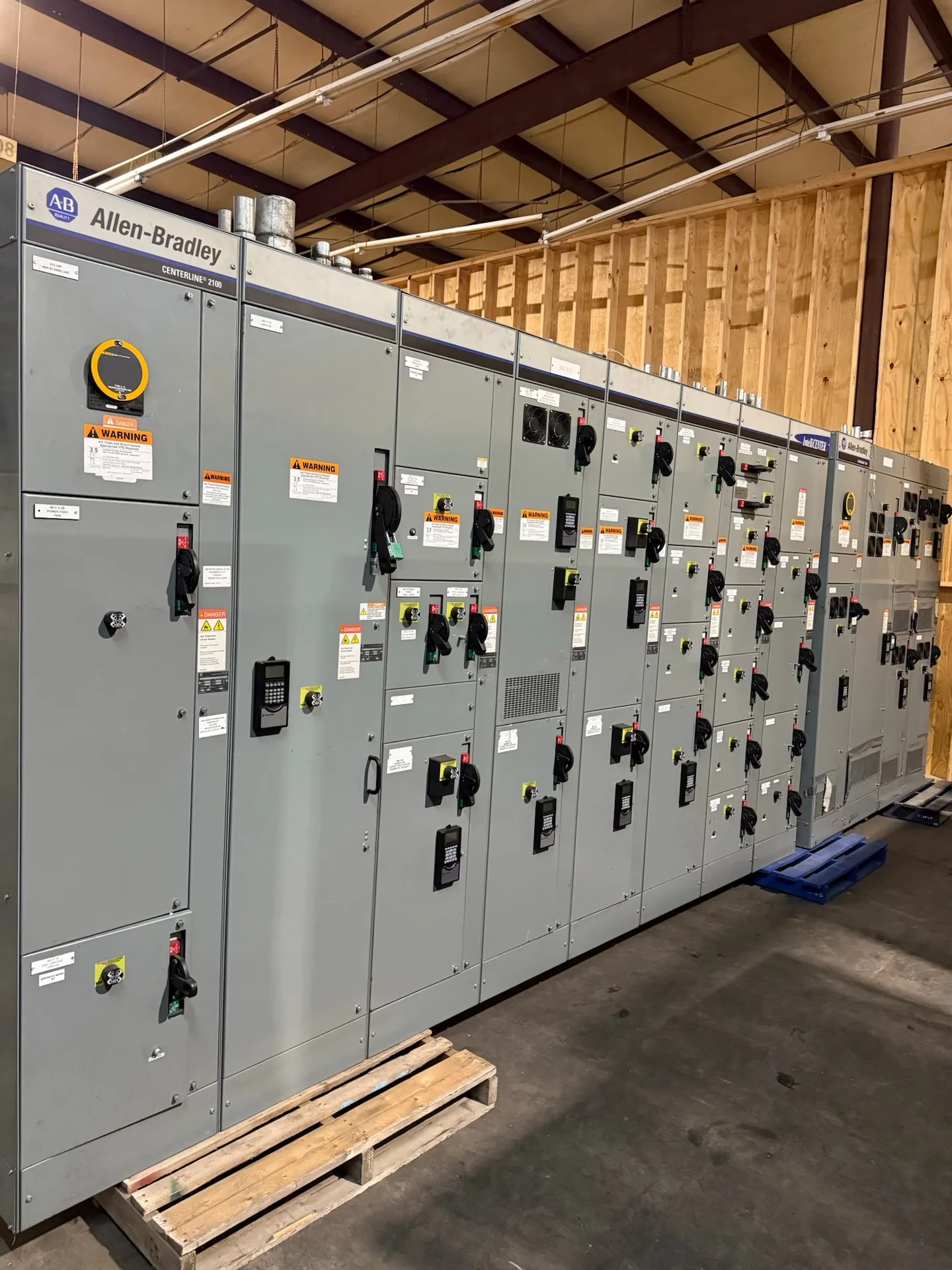
Consider compact gas-insulated equipment, insulating-medium requirements, monitoring, maintenance, and environmental compliance considerations. The equipment selection should follow the actual source characteristics, connected loads, operating requirements and installation environment. We manufacture new power distribution equipment in the United States and serve customers across North Carolina. Tell us what is known about the one-line, desired configuration and target delivery schedule. A project review establishes the proposed scope and identifies ratings or documentation that need confirmation.
Gas Insulated High Voltage Switchgear — project planning
Metal-clad switchgear is a specific form of metal-enclosed medium-voltage switchgear, not simply any assembly with a metal exterior. IEEE C37.20.2 describes metal-clad construction with drawout electrically operated circuit breakers and grounded metal barriers separating key compartments. For a project, specify the required voltage class, bus current, fault ratings, relay functions and number of feeders. Consider breaker handling, compartment access, control power and maintenance procedures when evaluating the layout. Request confirmation of the applicable standard and the proposed design's construction and ratings; do not assume arc-resistant performance without documented evidence.
Metal-enclosed interrupter switchgear can be considered for medium-voltage distribution where the switching and protection scheme suits the connected loads. A feeder may use a load-interrupter switch and fuses, subject to the selected equipment's ratings and application. Define whether the duty is transformer protection, cable switching or another function, and provide normal load current, fault current and required isolation. Review fuse coordination, visible isolation provisions, interlocks and space for terminations. Metal-enclosed does not automatically mean metal-clad; compare the specified compartmentation and devices against the applicable standard and maintenance plan.
High-Voltage Project Scoping
High-voltage projects require a separate review of the utility interface, insulation coordination, switching duties and site constraints; a low-voltage switchboard specification is not a substitute. Begin with a one-line diagram, nominal and maximum system voltages, grounding method, expected load and utility-provided fault information. Identify required equipment boundaries, protective relays, communications, metering and ownership of the interconnection. The project team should establish applicable standards, clearances, studies and permitting responsibilities for the specific voltage and installation. Equipment configuration and scope should be confirmed through a project-specific technical review.
UL 891 is a standard for dead-front switchboards rated 1,000 volts or less. It is not the standard used to establish requirements for switchgear rated above 1,000 volts; that equipment requires consideration of other applicable standards and ratings. For a switchboard project, the specified voltage, continuous current, short-circuit current rating, and intended service conditions must match the application. A UL 891 listing must not be assumed from the use of listed components or the mention of the standard. Verify any claimed listing for the actual assembly using its markings and certification documentation.
Prepare a Switchgear Inquiry
A complete inquiry helps the project team compare equipment on the same technical basis. Include a current one-line diagram, load schedule, system voltage and grounding, available fault current, desired protective devices and any coordination requirements. Add site dimensions, access restrictions, cable entry, enclosure exposure and utility requirements. Identify applicable codes and standards, required third-party listing or inspection, submittal drawings and requested test documentation. Reserve future capacity explicitly rather than assuming it is included. A qualified engineer should review the final design, protective settings and installation against the project's actual conditions.
Switchgear can expose workers to shock and arc-flash hazards even after a disconnect has been opened. Installation, testing, operation, and maintenance should be assigned to personnel qualified for the task and the equipment involved. Follow applicable OSHA requirements, the employer's safety procedures, and the equipment instructions. Establish an electrically safe work condition where required: identify all sources, de-energize, apply the required lockout and tagging procedures, and have a qualified person verify absence of voltage. Address stored energy and possible backfeeds. Energized work requires appropriate justification and protective measures under applicable rules.
Busbar Work: Preparing Reliable Joints
A busbar joint depends on compatible materials, prepared contact surfaces, specified hardware, and the correct installation method. Surface treatment and joint compounds, when required, should follow the assembly and component instructions rather than a generic recipe. Fasteners should be tightened to the specified torque using suitable tools, with access provided for inspection and maintenance. The same care applies to field-installed splice connections between shipping sections. Unapproved drilling, substitution, or rework can affect current carrying capacity, clearances, or short-circuit performance and should be reviewed before proceeding.
Location affects both switchgear design inputs and the practical work of getting equipment to its installation point. Identify indoor or outdoor placement, environmental exposure, site elevation, seismic design criteria where relevant, and any unusual transportation restrictions. The procurement package should describe delivery access, unloading responsibilities, storage conditions, and the available path through doors or other openings. Discuss shipping splits and field assembly requirements with the project team before finalizing the layout. Protect equipment from moisture and physical damage during transit and storage, following the applicable handling instructions.
Coordinate Protective Devices
Protection coordination considers how upstream and downstream devices respond to faults and overloads. The goal is often to isolate the affected circuit while keeping as much of the remaining system in service as practical. Where selective coordination is required, the engineer must evaluate the applicable devices across the required range of currents and operating times. Time-current curves, manufacturer coordination tables, available fault current, and actual trip settings may all matter. Share continuity requirements and relevant system information early; a high equipment rating or adjustable trip unit does not by itself prove selective coordination.
Short-circuit current rating, or SCCR, describes the fault current an assembly or component can withstand under specified conditions at a stated voltage. A breaker's or fuse's interrupting rating describes the fault current that device can safely interrupt under specified conditions. Both must be considered against the available fault current at the installation point; a high breaker rating alone does not establish the assembly rating. A qualified designer should also review any conditions attached to the equipment rating. Series-rated combinations require specific permitted device combinations and application checks, not an assumption based on the upstream breaker alone.
Start with the right specifications
Final capabilities and ratings are confirmed against the application, approved drawings and quotation.
| Project detail | What to provide |
|---|---|
| System | Voltage, phase, wiring and grounding |
| Current | Main and feeder ratings; load information |
| Protection | Available fault current, SCCR and protective device requirements |
| Installation | Enclosure, space, utility requirements and destination |