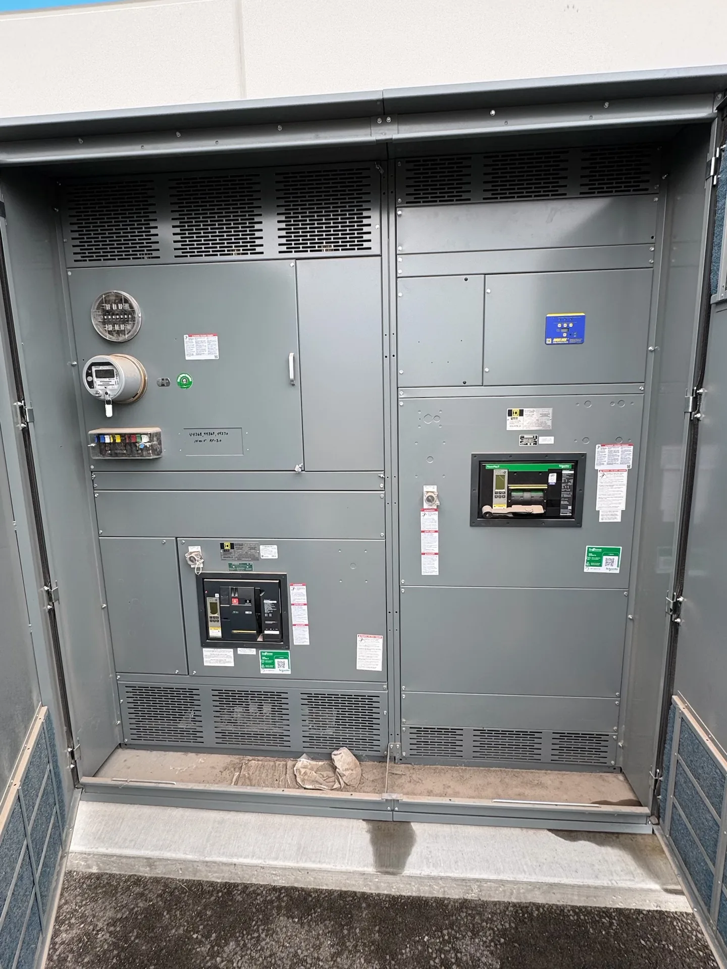
Plan spare feeder positions, bus capacity, future stages, operating constraints, and cutover of additional IT load. The equipment selection should follow the actual source characteristics, connected loads, operating requirements and installation environment. We manufacture new power distribution equipment in the United States and serve customers across North Carolina. Tell us what is known about the one-line, desired configuration and target delivery schedule. A project review establishes the proposed scope and identifies ratings or documentation that need confirmation.
Data Center Capacity Expansion Switchgear — project planning
Data center switchgear planning starts with a clear picture of critical computing loads, cooling equipment, and the paths that deliver power to each. Procurement documents should identify utility and generator sources, transfer arrangements, expected expansion, and the separation desired between redundant distribution paths. Ask the design team to evaluate fault levels, protective device coordination, and maintenance bypass needs before finalizing a lineup. Metering and communications requirements should be stated alongside physical constraints so operators can monitor distribution without treating an equipment description as a substitute for an engineered system.
Load continuity begins with understanding which services can tolerate an interruption and which require an alternate operating plan. Identify critical loads, available sources, transfer arrangements, and dependencies such as control power and cooling. The design team can then evaluate sectionalizing, protective coordination, and maintenance isolation against the project's operating objectives. Procurement documents should describe the intended switching sequence and any interlocks or monitoring interfaces. Backup equipment and redundant paths still require testing, maintenance, and documented operating procedures; neither should be treated as a guarantee of uninterrupted service.
Motor Control Centers
A motor control center groups motor starters and related control equipment so multiple motors can be operated and protected from an organized lineup. Provide a motor schedule with horsepower, voltage, full-load current, starting method and duty for each load. Specify disconnects, overload protection, starter type, control voltage and any variable-frequency drives or communication interfaces. Review heat dissipation, available fault current, feeder sizing and space for future units. Drawout construction, network features and spare compartments should be confirmed for the proposed design rather than assumed from the term MCC.
Phase design should begin with the source configuration and the voltage and phase requirements of the connected loads. Distinguish single-phase and three-phase loads, identify any neutral requirements, and provide the engineer with a realistic load schedule. Distribution planning should consider phase balance, nonlinear loads, conductor sizing, grounding, and the effect of motor starting on the system. Where multiple sources or transfer equipment are involved, document the neutral switching and grounding approach for coordinated review. Procurement drawings should communicate phase arrangement and termination requirements clearly to the installation team.
Custom Design: Establishing the Electrical Basis
A useful switchgear design starts with the electrical system, not the enclosure dimensions alone. The project team establishes nominal voltage, frequency, phase configuration, grounding method, expected loads, and available fault current at the installation point. These inputs guide equipment ratings, protective device selection, and the arrangement of incoming and outgoing circuits. Future feeders or alternate sources should be identified early because they can affect bus capacity and layout. The final design must also reflect the applicable codes, the site conditions, and the ratings of the complete assembly.
A submittal package gives the design and construction teams an opportunity to check the proposed equipment against the project documents. Depending on the contract, it may include drawings, device data sheets, ratings, enclosure details, metering information, and certification documentation. Agree on the required contents and the review sequence before ordering. The engineer, contractor, owner, and utility may each need to review different items. Consolidate comments, track revisions, and return a clear disposition to the supplier. Submittal review does not replace the separate inspections and approvals required for installation.
Use a Fault Study to Set Ratings
A short-circuit study estimates the fault current available at points throughout the electrical system. The engineer may need utility source data, transformer ratings and impedances, conductor lengths and sizes, motor contributions, and information about generators or other sources. Different operating configurations can produce different results. Provide the study or the project's specified fault-current requirements with the quote request so the proposed assembly and protective devices can be evaluated against the expected duty. Revisit the study when sources, equipment, or system arrangements change; a preliminary figure is not a substitute for the completed engineering review.
Before selecting equipment dimensions, check the electrical room for the working space and access needed around the proposed assembly. Required clearance depends on the applicable code, voltage, equipment arrangement, and conditions at the installation. Door swing, rear access when needed, ventilation, equipment removal, and entry or egress also affect the layout. Compare the manufacturer's drawings with architectural and mechanical plans, including nearby piping and other obstructions. The engineer and authority having jurisdiction should confirm applicable requirements, and the completed working space must remain unobstructed rather than becoming storage.
Retrofits: New Equipment for an Existing System
A retrofit project may call for new equipment that connects to an existing electrical system while respecting established building constraints. Useful starting information includes current single-line drawings, available fault current, feeder sizes, connection locations, and the physical route into the room. Existing records should be checked against verified site conditions because past modifications may not appear on drawings. The new assembly's ratings and interfaces must be evaluated for the intended installation. Outage sequencing and the boundaries between the new equipment and existing infrastructure should be agreed with the project team.
Modernization can involve supplying a new switchgear or switchboard lineup for a project that needs updated distribution, monitoring, or control functions. The design may incorporate metering, protective relays, communications interfaces, or provisions for future circuits when specified. Each addition needs a defined purpose, power source, wiring interface, and compatibility review. Existing upstream and downstream equipment also influences fault protection and operating sequences. Before the design is finalized, the project team should confirm responsibility for system studies, integration, installation, and acceptance so that new equipment fits the overall plan.
Start with the right specifications
Final capabilities and ratings are confirmed against the application, approved drawings and quotation.
| Project detail | What to provide |
|---|---|
| System | Voltage, phase, wiring and grounding |
| Current | Main and feeder ratings; load information |
| Protection | Available fault current, SCCR and protective device requirements |
| Installation | Enclosure, space, utility requirements and destination |