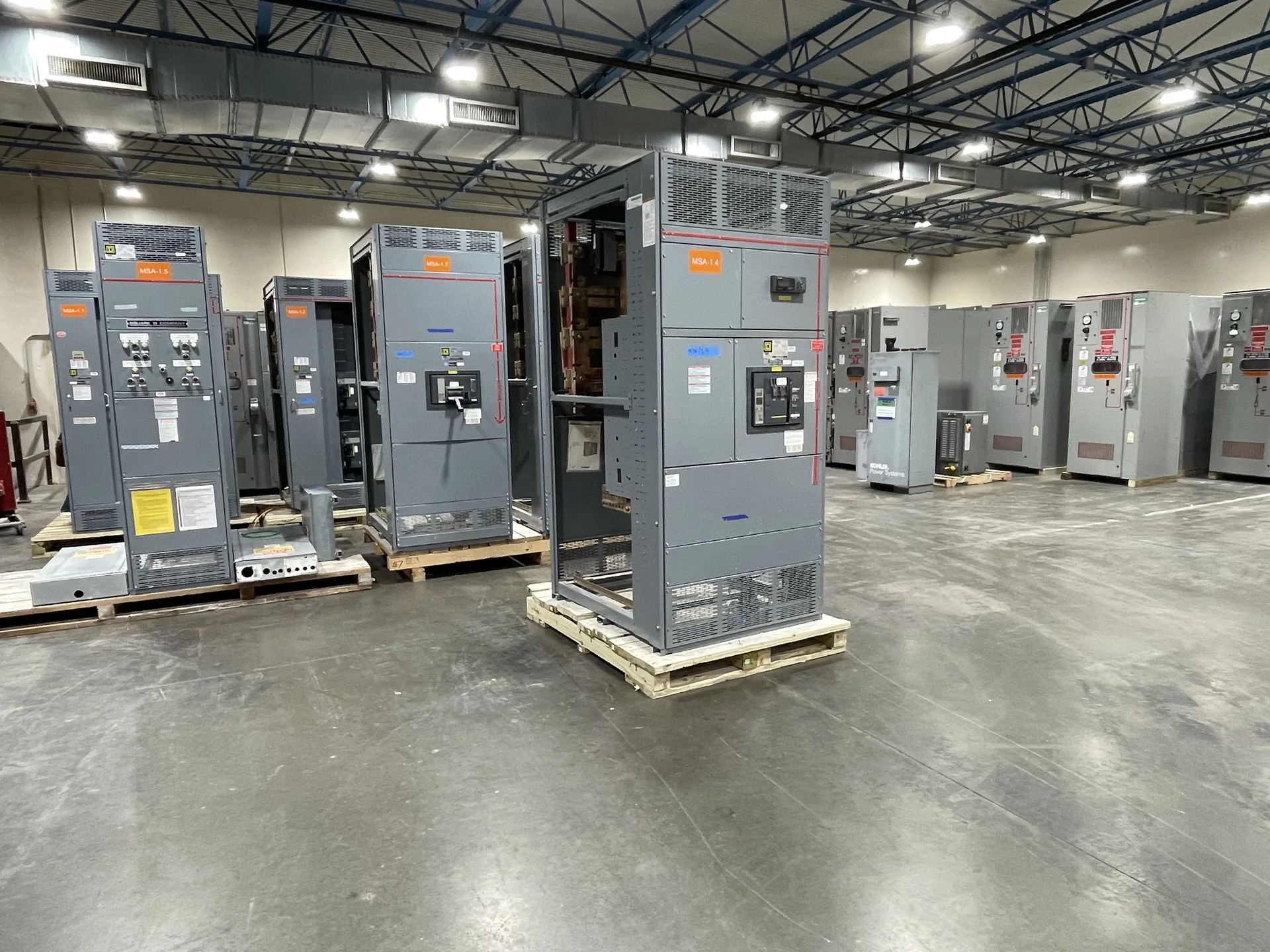
Consider independent power-path architecture, separation, failure modes, maintenance access, and site-specific availability targets. The equipment selection should follow the actual source characteristics, connected loads, operating requirements and installation environment. We manufacture new power distribution equipment in the United States and serve customers across North Carolina. Tell us what is known about the one-line, desired configuration and target delivery schedule. A project review establishes the proposed scope and identifies ratings or documentation that need confirmation.
Data Center A and B Power Paths — project planning
Data center switchgear planning starts with a clear picture of critical computing loads, cooling equipment, and the paths that deliver power to each. Procurement documents should identify utility and generator sources, transfer arrangements, expected expansion, and the separation desired between redundant distribution paths. Ask the design team to evaluate fault levels, protective device coordination, and maintenance bypass needs before finalizing a lineup. Metering and communications requirements should be stated alongside physical constraints so operators can monitor distribution without treating an equipment description as a substitute for an engineered system.
Switchgear layouts should give qualified personnel a practical way to inspect, test, isolate, and maintain equipment over its service life. Show required working space, door swing, cable access, and the route for removing major components on the project drawings. Identify isolation points and any alternate feeds or control-power sources that could leave parts energized. Procurement specifications can request durable labeling, accessible test provisions, and documentation of operating sequences. Maintenance plans should use site-specific procedures for controlling hazardous energy and verifying absence of voltage before work begins.
Enclosure and Site Selection
Enclosure selection starts with the actual location and exposure, not simply an indoor or outdoor label. Specify ambient temperature, altitude, humidity, dust, corrosive agents, water exposure and any washdown or ventilation needs. NEMA Type 1 is generally intended for indoor use, while Type 3R is commonly selected for certain outdoor weather exposures; confirm that the chosen type meets the full site conditions. Account for heaters, drainage, cable entry, working clearances and maintenance access where applicable. An environmental enclosure rating alone does not establish an arc-resistant rating or a specific equipment certification.
Sheet metal fabrication turns an equipment layout into the structural and protective enclosure around electrical components. Cutouts, formed panels, mounting surfaces, doors, and covers must align with the intended devices and cable paths. Material selection and finish depend on the specified environment, including indoor or outdoor exposure and corrosion concerns. Edges and openings should be finished to avoid damage to conductors and injury during handling. Enclosure modifications can affect strength, protection, ventilation, or a documented rating, so changes require review against the applicable design and instructions.
Assembly: Building a Coordinated Equipment Lineup
Switchgear assembly brings structural sections, protective devices, bus supports, barriers, and control components together according to the approved drawings. Fit matters: door alignment, device mounting, mechanical interlocks, and access to connections affect how the completed equipment can be operated and maintained. Components should be installed within their ratings and in accordance with their instructions and the assembly design. Section joints and removable parts need clear identification for installation. Any design change made during assembly should be reviewed and documented before it becomes part of the final configuration.
A lead-time estimate is more useful when its starting point and milestones are clear. Ask whether the estimate begins at order acceptance, receipt of required commercial information, approval of drawings, or release for production. Break the schedule into engineering, customer review, component procurement, assembly, inspection, and freight. Breakers, metering, special enclosures, and design changes can affect the schedule, as can delayed approvals. Share the required on-site date and any outage or construction constraints. Request an updated schedule when assumptions change, and distinguish an estimate from a confirmed commitment.
Custom Design: Planning the Physical Layout
A project-specific equipment layout connects electrical requirements to the space available for installation and maintenance. Section dimensions, cable entry, conductor bending space, ventilation, and access to operating devices all influence the arrangement. The design should account for doors, removable covers, lifting provisions, and the working clearances required at the installed location. Coordination with the building team helps identify obstructions, floor loading, and the route into the electrical room. A documented layout also makes it easier to review future expansion without assuming unused space is automatically suitable for additional equipment.
Commissioning brings the equipment and the wider installation together through a planned sequence of checks before service. The project team should confirm anchorage, accessible clearances, cable terminations, grounding, section splices, and control connections against the drawings and installation instructions. Utility interfaces, protective device settings, and remote signals may require coordination with other parties. Responsibilities for tests, documentation, and energization should be established in advance. Work on electrical equipment must follow applicable safety requirements, including deenergization, lockout or tagging, and verification of the deenergized condition where required.
Project Location and Shipping
Location affects both switchgear design inputs and the practical work of getting equipment to its installation point. Identify indoor or outdoor placement, environmental exposure, site elevation, seismic design criteria where relevant, and any unusual transportation restrictions. The procurement package should describe delivery access, unloading responsibilities, storage conditions, and the available path through doors or other openings. Discuss shipping splits and field assembly requirements with the project team before finalizing the layout. Protect equipment from moisture and physical damage during transit and storage, following the applicable handling instructions.
Phase design should begin with the source configuration and the voltage and phase requirements of the connected loads. Distinguish single-phase and three-phase loads, identify any neutral requirements, and provide the engineer with a realistic load schedule. Distribution planning should consider phase balance, nonlinear loads, conductor sizing, grounding, and the effect of motor starting on the system. Where multiple sources or transfer equipment are involved, document the neutral switching and grounding approach for coordinated review. Procurement drawings should communicate phase arrangement and termination requirements clearly to the installation team.
Start with the right specifications
Final capabilities and ratings are confirmed against the application, approved drawings and quotation.
| Project detail | What to provide |
|---|---|
| System | Voltage, phase, wiring and grounding |
| Current | Main and feeder ratings; load information |
| Protection | Available fault current, SCCR and protective device requirements |
| Installation | Enclosure, space, utility requirements and destination |