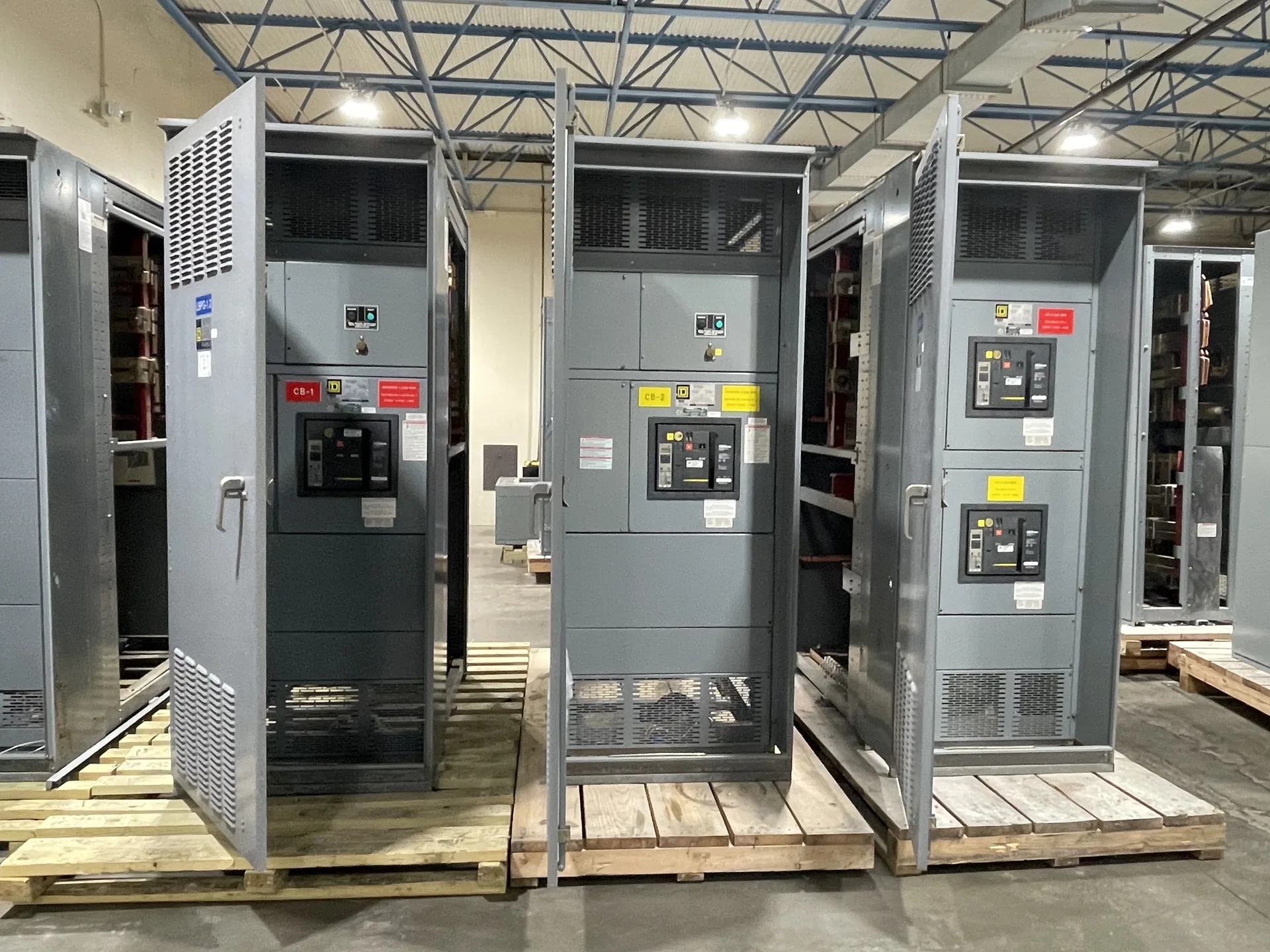
Consider a breaker’s interrupting rating and distinguish it from the switchgear assembly SCCR and system available fault current. Useful specifications connect the source, protective devices, feeders and physical installation rather than treating each in isolation. Our team builds and supplies new equipment in the USA for North Carolina projects. Provide the information available now, including the intended voltage, current, environment and delivery needs. The engineer of record and the manufacturer can then identify what remains to be clarified before a project-specific quotation.
Circuit Breaker Interrupting Rating — project planning
Available fault current is a property of the electrical system at a particular point; interrupting and short-circuit ratings describe equipment capability. Check each breaker or fuse's interrupting rating at the applied voltage against the fault current it may need to interrupt. Separately verify the assembly's short-circuit current or withstand rating and any associated time, device or installation conditions. Include contributions from utility sources, generators and motors as applicable to the study. Series-rated device combinations require documented compatibility and application in accordance with their conditions, not an assumption based on individual ampere ratings.
Short-circuit current rating, or SCCR, describes the fault current an assembly or component can withstand under specified conditions at a stated voltage. A breaker's or fuse's interrupting rating describes the fault current that device can safely interrupt under specified conditions. Both must be considered against the available fault current at the installation point; a high breaker rating alone does not establish the assembly rating. A qualified designer should also review any conditions attached to the equipment rating. Series-rated combinations require specific permitted device combinations and application checks, not an assumption based on the upstream breaker alone.
Use a Fault Study to Set Ratings
A short-circuit study estimates the fault current available at points throughout the electrical system. The engineer may need utility source data, transformer ratings and impedances, conductor lengths and sizes, motor contributions, and information about generators or other sources. Different operating configurations can produce different results. Provide the study or the project's specified fault-current requirements with the quote request so the proposed assembly and protective devices can be evaluated against the expected duty. Revisit the study when sources, equipment, or system arrangements change; a preliminary figure is not a substitute for the completed engineering review.
Panelboards distribute power to branch circuits and can serve lighting, receptacle or equipment loads when properly selected. A useful schedule identifies system voltage, phase, wire count, main or main-lug configuration, branch circuit quantities and protective device ratings. Review available fault current at the panel location, the assembly rating and the interrupting ratings of installed breakers. Neutral capacity deserves particular attention where load imbalance or harmonics are expected. Reserve space for identified future circuits, and coordinate enclosure mounting, conductor entry, circuit labeling and required access with the installation drawings.
Know What UL 891 Covers
UL 891 is a safety standard for switchboards; it is not a blanket certification for every product a manufacturer offers. Low-voltage power circuit breaker switchgear is addressed by a different standard, UL 1558, so identify the specified equipment type rather than treating the terms as interchangeable. An individual assembly's certification, voltage, continuous current, and short-circuit ratings depend on its design and applicable certification scope. A manufacturer's UL 891 general coverage program may have limits that differ from those of the standard itself. Request documentation for the specific proposed configuration and its ratings.
Engineering review compares the proposed equipment with the project's electrical and physical requirements before construction proceeds. The review can address single-line diagrams, device ratings, available fault current, grounding, control interfaces, enclosure selection, and installation constraints. Protective device settings and coordination depend on the broader power system and may require separate studies by the responsible design professional. Drawing revisions and equipment substitutions should be tracked so all parties work from the same information. Approval of a drawing alone does not replace required product evaluation, inspection, or authority approval.
Find the Right Supplier
Start with suppliers that offer the type of new equipment and voltage class specified for your project. Give each candidate the same one-line, specifications, delivery location, and schedule so their proposals can be compared fairly. Ask about design support, the proposed assembly's ratings and certification, component sourcing, documentation, and warranty process. Request confirmation of the sales channel and the person responsible for changes after order placement. Evaluate technical fit and responsiveness as well as price; a proposal that clearly identifies assumptions and exclusions is easier for your project team to review.
Switchgear assembly brings structural sections, protective devices, bus supports, barriers, and control components together according to the approved drawings. Fit matters: door alignment, device mounting, mechanical interlocks, and access to connections affect how the completed equipment can be operated and maintained. Components should be installed within their ratings and in accordance with their instructions and the assembly design. Section joints and removable parts need clear identification for installation. Any design change made during assembly should be reviewed and documented before it becomes part of the final configuration.
Discuss Lead Time Before Ordering
A lead-time estimate is more useful when its starting point and milestones are clear. Ask whether the estimate begins at order acceptance, receipt of required commercial information, approval of drawings, or release for production. Break the schedule into engineering, customer review, component procurement, assembly, inspection, and freight. Breakers, metering, special enclosures, and design changes can affect the schedule, as can delayed approvals. Share the required on-site date and any outage or construction constraints. Request an updated schedule when assumptions change, and distinguish an estimate from a confirmed commitment.
A busbar joint depends on compatible materials, prepared contact surfaces, specified hardware, and the correct installation method. Surface treatment and joint compounds, when required, should follow the assembly and component instructions rather than a generic recipe. Fasteners should be tightened to the specified torque using suitable tools, with access provided for inspection and maintenance. The same care applies to field-installed splice connections between shipping sections. Unapproved drilling, substitution, or rework can affect current carrying capacity, clearances, or short-circuit performance and should be reviewed before proceeding.
Start with the right specifications
Final capabilities and ratings are confirmed against the application, approved drawings and quotation.
| Project detail | What to provide |
|---|---|
| System | Voltage, phase, wiring and grounding |
| Current | Main and feeder ratings; load information |
| Protection | Available fault current, SCCR and protective device requirements |
| Installation | Enclosure, space, utility requirements and destination |