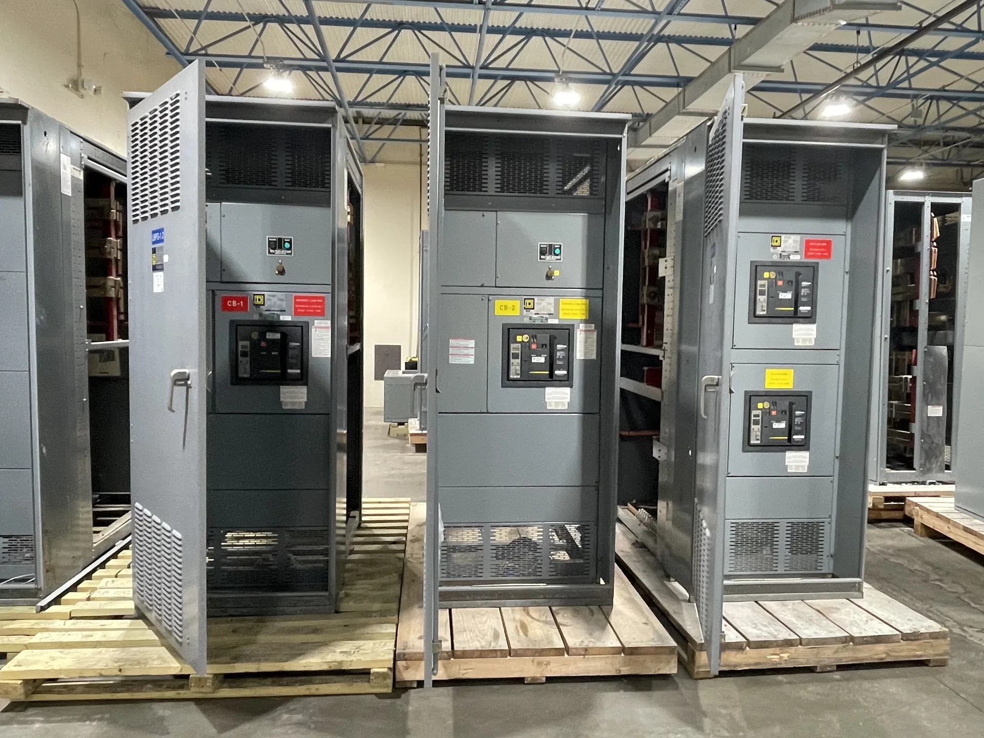
A busbar is a conductive bar or similar conductor that carries and distributes current within electrical equipment. It connects incoming power to devices or other sections of a distribution assembly. Material, dimensions, joints, support, and spacing determine its continuous-current and short-circuit withstand capabilities for the particular design. The starting point is the actual electrical system and how the lineup will be installed and operated. We build and supply new power distribution equipment in the United States for North Carolina projects. Share the intended ratings, application, available space and schedule with our team so they can be evaluated against the proposed scope. The final configuration, availability and delivery details are established in the project quotation.
Busbar Glossary Definition — project planning
Busbars distribute power within an assembly and must be designed as part of the complete electrical system. Conductor material, cross section, temperature rise, spacing, insulation, and support arrangement all affect suitability for the intended duty. The design must also account for mechanical forces associated with the specified short-circuit rating. Bending, punching, and routing should follow the approved construction details rather than rules of thumb alone. Phase identification and clear section interfaces help installers connect a lineup correctly while preserving required clearances and access.
A useful switchgear design starts with the electrical system, not the enclosure dimensions alone. The project team establishes nominal voltage, frequency, phase configuration, grounding method, expected loads, and available fault current at the installation point. These inputs guide equipment ratings, protective device selection, and the arrangement of incoming and outgoing circuits. Future feeders or alternate sources should be identified early because they can affect bus capacity and layout. The final design must also reflect the applicable codes, the site conditions, and the ratings of the complete assembly.
Custom Design: Planning the Physical Layout
A project-specific equipment layout connects electrical requirements to the space available for installation and maintenance. Section dimensions, cable entry, conductor bending space, ventilation, and access to operating devices all influence the arrangement. The design should account for doors, removable covers, lifting provisions, and the working clearances required at the installed location. Coordination with the building team helps identify obstructions, floor loading, and the route into the electrical room. A documented layout also makes it easier to review future expansion without assuming unused space is automatically suitable for additional equipment.
Phase design should begin with the source configuration and the voltage and phase requirements of the connected loads. Distinguish single-phase and three-phase loads, identify any neutral requirements, and provide the engineer with a realistic load schedule. Distribution planning should consider phase balance, nonlinear loads, conductor sizing, grounding, and the effect of motor starting on the system. Where multiple sources or transfer equipment are involved, document the neutral switching and grounding approach for coordinated review. Procurement drawings should communicate phase arrangement and termination requirements clearly to the installation team.
Plan for Final Acceptance
Final acceptance involves more than receiving a shipment or approving a drawing. Establish the required factory documentation, delivery inspection, installation checks, field tests, and commissioning responsibilities in the contract. Compare nameplate information and the installed configuration with approved documents, and resolve outstanding punch-list items. The installing contractor and qualified testing personnel should complete the checks assigned to them before energization. Coordinate utility requirements and inspection by the authority having jurisdiction when applicable. Document the results and obtain the approvals required by the project; no single review automatically substitutes for all others.
A lead-time estimate is more useful when its starting point and milestones are clear. Ask whether the estimate begins at order acceptance, receipt of required commercial information, approval of drawings, or release for production. Break the schedule into engineering, customer review, component procurement, assembly, inspection, and freight. Breakers, metering, special enclosures, and design changes can affect the schedule, as can delayed approvals. Share the required on-site date and any outage or construction constraints. Request an updated schedule when assumptions change, and distinguish an estimate from a confirmed commitment.
Prepare a Switchgear Quote Request
A useful quote request begins with the latest one-line diagram, project location, system voltage, phase and wire configuration, and required continuous current. Include available fault current or the engineer's required short-circuit rating, the number and ratings of incoming and outgoing circuits, and whether the equipment serves as service entrance or downstream distribution. Share enclosure requirements, metering, communications, spare capacity, and preferred delivery dates. Attach specifications and identify open questions rather than guessing. A complete package helps the manufacturer identify assumptions, compare options, and return a quote suited to the new equipment your project needs.
A busbar joint depends on compatible materials, prepared contact surfaces, specified hardware, and the correct installation method. Surface treatment and joint compounds, when required, should follow the assembly and component instructions rather than a generic recipe. Fasteners should be tightened to the specified torque using suitable tools, with access provided for inspection and maintenance. The same care applies to field-installed splice connections between shipping sections. Unapproved drilling, substitution, or rework can affect current carrying capacity, clearances, or short-circuit performance and should be reviewed before proceeding.
Arrange Nationwide Shipping
For projects across the United States, discuss freight requirements before accepting a delivery estimate. Provide the destination, site access restrictions, required delivery window, and whether a loading dock, forklift, or rigging crew is available. Ask how the assembly will be divided and packaged, who arranges unloading, and which freight and insurance terms apply. Confirm any special handling, storage, or weather protection needs with the supplier. On arrival, check the shipment against the packing list and document visible damage on the carrier's paperwork. Report suspected concealed damage promptly under the applicable claim procedures.
Engineering review compares the proposed equipment with the project's electrical and physical requirements before construction proceeds. The review can address single-line diagrams, device ratings, available fault current, grounding, control interfaces, enclosure selection, and installation constraints. Protective device settings and coordination depend on the broader power system and may require separate studies by the responsible design professional. Drawing revisions and equipment substitutions should be tracked so all parties work from the same information. Approval of a drawing alone does not replace required product evaluation, inspection, or authority approval.
Start with the right specifications
Final capabilities and ratings are confirmed against the application, approved drawings and quotation.
| Project detail | What to provide |
|---|---|
| System | Voltage, phase, wiring and grounding |
| Current | Main and feeder ratings; load information |
| Protection | Available fault current, SCCR and protective device requirements |
| Installation | Enclosure, space, utility requirements and destination |