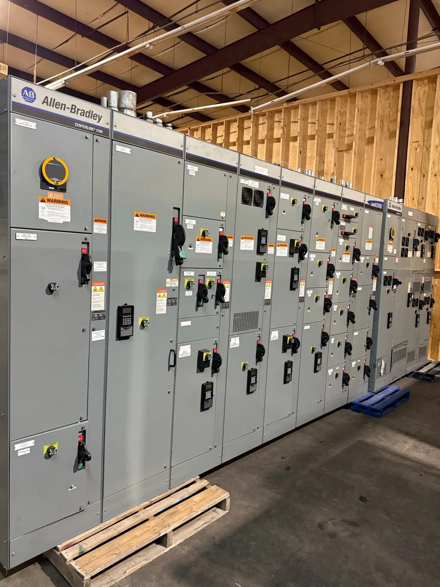
Identify security-system loads, UPS or standby interfaces, segmentation, testing, and operational responsibilities. The equipment selection should follow the actual source characteristics, connected loads, operating requirements and installation environment. We manufacture new power distribution equipment in the United States and serve customers across North Carolina. Tell us what is known about the one-line, desired configuration and target delivery schedule. A project review establishes the proposed scope and identifies ratings or documentation that need confirmation.
Airport Security System Backup Distribution — project planning
Load continuity begins with understanding which services can tolerate an interruption and which require an alternate operating plan. Identify critical loads, available sources, transfer arrangements, and dependencies such as control power and cooling. The design team can then evaluate sectionalizing, protective coordination, and maintenance isolation against the project's operating objectives. Procurement documents should describe the intended switching sequence and any interlocks or monitoring interfaces. Backup equipment and redundant paths still require testing, maintenance, and documented operating procedures; neither should be treated as a guarantee of uninterrupted service.
Airport electrical systems may support terminal operations, baggage handling, communications, airfield-related equipment, and other services with different operating priorities. A switchgear procurement package should distinguish these loads, identify source and transfer interfaces, and describe the desired monitoring and control connections. The project team should review feeder routing and opportunities to isolate sections for maintenance. Equipment delivery and access plans should account for security procedures and constrained routes within the project area. Coordinate switching activities with the responsible airport stakeholders rather than assuming every system can be interrupted together.
Utility Distribution Interfaces
Utility-facing switchgear projects require early coordination over the boundary between the utility system and customer-owned distribution. The procurement package should identify the point of connection, incoming source characteristics, metering arrangements, protection responsibilities, and the information needed for the utility's review. Show current and voltage transformer locations where applicable, along with communication and control interfaces. Confirm assumptions about available fault current and future system changes with the responsible parties. Clear ownership and operating responsibilities help avoid gaps when equipment is commissioned, switched, or maintained.
Phase design should begin with the source configuration and the voltage and phase requirements of the connected loads. Distinguish single-phase and three-phase loads, identify any neutral requirements, and provide the engineer with a realistic load schedule. Distribution planning should consider phase balance, nonlinear loads, conductor sizing, grounding, and the effect of motor starting on the system. Where multiple sources or transfer equipment are involved, document the neutral switching and grounding approach for coordinated review. Procurement drawings should communicate phase arrangement and termination requirements clearly to the installation team.
Custom Design: Planning the Physical Layout
A project-specific equipment layout connects electrical requirements to the space available for installation and maintenance. Section dimensions, cable entry, conductor bending space, ventilation, and access to operating devices all influence the arrangement. The design should account for doors, removable covers, lifting provisions, and the working clearances required at the installed location. Coordination with the building team helps identify obstructions, floor loading, and the route into the electrical room. A documented layout also makes it easier to review future expansion without assuming unused space is automatically suitable for additional equipment.
A complete inquiry helps the project team compare equipment on the same technical basis. Include a current one-line diagram, load schedule, system voltage and grounding, available fault current, desired protective devices and any coordination requirements. Add site dimensions, access restrictions, cable entry, enclosure exposure and utility requirements. Identify applicable codes and standards, required third-party listing or inspection, submittal drawings and requested test documentation. Reserve future capacity explicitly rather than assuming it is included. A qualified engineer should review the final design, protective settings and installation against the project's actual conditions.
Inspection and Testing: Verifying Assembly Details
Inspection provides a structured way to compare an assembled lineup with its approved drawings and component instructions. A review can include device identification, conductor routing, barriers, grounding connections, hardware, labels, and the condition of the enclosure. Mechanical checks may cover door operation, interlocks, and the fit of removable sections where applicable. Findings should be documented and resolved before release. The inspection scope and acceptance criteria belong in the project documentation, because a visual check alone cannot establish every electrical rating or demonstrate performance under fault conditions.
The price of new distribution equipment depends on its electrical ratings, physical construction, and included components. Main and feeder device types, bus material and capacity, short-circuit requirements, enclosure rating, metering, controls, and spare provisions can all affect the proposal. Engineering, testing, special documentation, freight, and site services may be included or quoted separately. Provide comparable specifications to each supplier and review exclusions, alternates, and payment terms alongside the base price. If the design is incomplete, ask which assumptions are driving the estimate and what could change when the drawings are finalized.
Custom Design: Establishing the Electrical Basis
A useful switchgear design starts with the electrical system, not the enclosure dimensions alone. The project team establishes nominal voltage, frequency, phase configuration, grounding method, expected loads, and available fault current at the installation point. These inputs guide equipment ratings, protective device selection, and the arrangement of incoming and outgoing circuits. Future feeders or alternate sources should be identified early because they can affect bus capacity and layout. The final design must also reflect the applicable codes, the site conditions, and the ratings of the complete assembly.
Switchgear layouts should give qualified personnel a practical way to inspect, test, isolate, and maintain equipment over its service life. Show required working space, door swing, cable access, and the route for removing major components on the project drawings. Identify isolation points and any alternate feeds or control-power sources that could leave parts energized. Procurement specifications can request durable labeling, accessible test provisions, and documentation of operating sequences. Maintenance plans should use site-specific procedures for controlling hazardous energy and verifying absence of voltage before work begins.
Start with the right specifications
Final capabilities and ratings are confirmed against the application, approved drawings and quotation.
| Project detail | What to provide |
|---|---|
| System | Voltage, phase, wiring and grounding |
| Current | Main and feeder ratings; load information |
| Protection | Available fault current, SCCR and protective device requirements |
| Installation | Enclosure, space, utility requirements and destination |