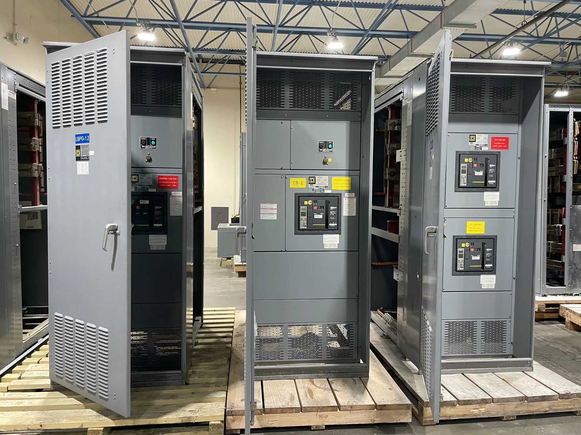
Scope gate power equipment feeders, load characteristics, location, protection, and terminal-to-apron interfaces. Useful specifications connect the source, protective devices, feeders and physical installation rather than treating each in isolation. Our team builds and supplies new equipment in the USA for North Carolina projects. Provide the information available now, including the intended voltage, current, environment and delivery needs. The engineer of record and the manufacturer can then identify what remains to be clarified before a project-specific quotation.
Airport Gate Ground Power Distribution — project planning
Airport electrical systems may support terminal operations, baggage handling, communications, airfield-related equipment, and other services with different operating priorities. A switchgear procurement package should distinguish these loads, identify source and transfer interfaces, and describe the desired monitoring and control connections. The project team should review feeder routing and opportunities to isolate sections for maintenance. Equipment delivery and access plans should account for security procedures and constrained routes within the project area. Coordinate switching activities with the responsible airport stakeholders rather than assuming every system can be interrupted together.
Utility-facing switchgear projects require early coordination over the boundary between the utility system and customer-owned distribution. The procurement package should identify the point of connection, incoming source characteristics, metering arrangements, protection responsibilities, and the information needed for the utility's review. Show current and voltage transformer locations where applicable, along with communication and control interfaces. Confirm assumptions about available fault current and future system changes with the responsible parties. Clear ownership and operating responsibilities help avoid gaps when equipment is commissioned, switched, or maintained.
Load Continuity and Switching
Load continuity begins with understanding which services can tolerate an interruption and which require an alternate operating plan. Identify critical loads, available sources, transfer arrangements, and dependencies such as control power and cooling. The design team can then evaluate sectionalizing, protective coordination, and maintenance isolation against the project's operating objectives. Procurement documents should describe the intended switching sequence and any interlocks or monitoring interfaces. Backup equipment and redundant paths still require testing, maintenance, and documented operating procedures; neither should be treated as a guarantee of uninterrupted service.
Location affects both switchgear design inputs and the practical work of getting equipment to its installation point. Identify indoor or outdoor placement, environmental exposure, site elevation, seismic design criteria where relevant, and any unusual transportation restrictions. The procurement package should describe delivery access, unloading responsibilities, storage conditions, and the available path through doors or other openings. Discuss shipping splits and field assembly requirements with the project team before finalizing the layout. Protect equipment from moisture and physical damage during transit and storage, following the applicable handling instructions.
Arrange Nationwide Shipping
For projects across the United States, discuss freight requirements before accepting a delivery estimate. Provide the destination, site access restrictions, required delivery window, and whether a loading dock, forklift, or rigging crew is available. Ask how the assembly will be divided and packaged, who arranges unloading, and which freight and insurance terms apply. Confirm any special handling, storage, or weather protection needs with the supplier. On arrival, check the shipment against the packing list and document visible damage on the carrier's paperwork. Report suspected concealed damage promptly under the applicable claim procedures.
Shipment planning considers the size, weight, center of gravity, and handling needs of each equipment section. A lineup may be divided into shipping sections when required by transportation limits or the path into the building. Documentation should identify section order, loose components, splice materials, and any handling or storage instructions supplied with the equipment. Packaging and protection should reflect the expected transit and storage conditions without assuming the enclosure alone is adequate for outdoor storage. On arrival, the receiving team should inspect for damage and document discrepancies before installation.
Coordinate Installation Before Delivery
Installation planning starts with the approved equipment dimensions, shipping splits, weights, and manufacturer's handling instructions. Check the route from the unloading point to the electrical room, including doors, elevators, floor loading, rigging access, and the final equipment pad or supports. Coordinate conduit locations, cable bending space, grounding, utility interfaces, and any required shutdown with the responsible trades. Define who will store, assemble, install, test, and commission the equipment. Arrange inspections and any required permits before energization. Early coordination can reveal access or sequencing problems while there is still time to address them.
Neutral and grounding arrangements affect the equipment design as well as the installation. Identify the system configuration, neutral conductor needs, ground bus, service or feeder application, and any ground-fault protection requirements. The electrical engineer should specify where neutral-to-ground bonding is required and where the neutral must remain isolated, using the adopted code and the actual source configuration. Transformers and generator transfer arrangements can introduce separately derived system questions. Provide these details before drawings are approved, and do not assume that a bonding arrangement suitable at one location is appropriate everywhere downstream.
Project Drawings and Submittals
Clear drawings help a switchgear supplier and the design team resolve interfaces before equipment is released for fabrication. Include a current one-line diagram, source information, feeder schedule, short-circuit study assumptions when available, and the intended control and metering functions. Physical drawings should identify room dimensions, cable entry, equipment clearances, and relevant obstructions. Request submittals that show lineup arrangement, connection details, device functions, and proposed departures from the specification. Review comments should be reconciled with the engineer of record and other affected trades before fabrication proceeds.
Busbars distribute power within an assembly and must be designed as part of the complete electrical system. Conductor material, cross section, temperature rise, spacing, insulation, and support arrangement all affect suitability for the intended duty. The design must also account for mechanical forces associated with the specified short-circuit rating. Bending, punching, and routing should follow the approved construction details rather than rules of thumb alone. Phase identification and clear section interfaces help installers connect a lineup correctly while preserving required clearances and access.
Start with the right specifications
Final capabilities and ratings are confirmed against the application, approved drawings and quotation.
| Project detail | What to provide |
|---|---|
| System | Voltage, phase, wiring and grounding |
| Current | Main and feeder ratings; load information |
| Protection | Available fault current, SCCR and protective device requirements |
| Installation | Enclosure, space, utility requirements and destination |