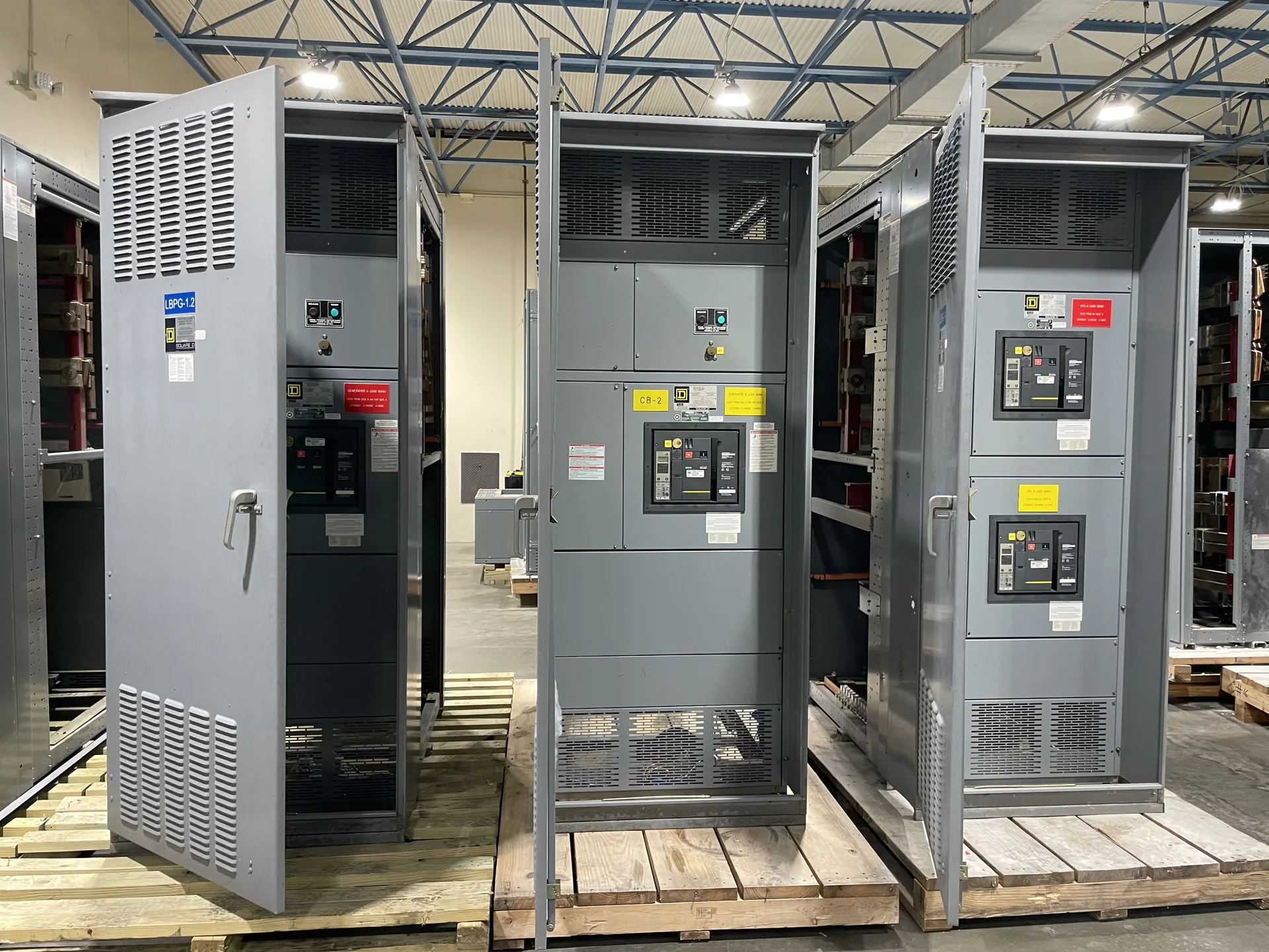
Consider air-insulated metal-enclosed construction, clearances, environmental conditions, maintenance, and space requirements. Useful specifications connect the source, protective devices, feeders and physical installation rather than treating each in isolation. Our team builds and supplies new equipment in the USA for North Carolina projects. Provide the information available now, including the intended voltage, current, environment and delivery needs. The engineer of record and the manufacturer can then identify what remains to be clarified before a project-specific quotation.
Air Insulated Metal Enclosed Switchgear — project planning
Metal-enclosed interrupter switchgear can be considered for medium-voltage distribution where the switching and protection scheme suits the connected loads. A feeder may use a load-interrupter switch and fuses, subject to the selected equipment's ratings and application. Define whether the duty is transformer protection, cable switching or another function, and provide normal load current, fault current and required isolation. Review fuse coordination, visible isolation provisions, interlocks and space for terminations. Metal-enclosed does not automatically mean metal-clad; compare the specified compartmentation and devices against the applicable standard and maintenance plan.
Metal-clad switchgear is a specific form of metal-enclosed medium-voltage switchgear, not simply any assembly with a metal exterior. IEEE C37.20.2 describes metal-clad construction with drawout electrically operated circuit breakers and grounded metal barriers separating key compartments. For a project, specify the required voltage class, bus current, fault ratings, relay functions and number of feeders. Consider breaker handling, compartment access, control power and maintenance procedures when evaluating the layout. Request confirmation of the applicable standard and the proposed design's construction and ratings; do not assume arc-resistant performance without documented evidence.
Reserve Working Clearances
Before selecting equipment dimensions, check the electrical room for the working space and access needed around the proposed assembly. Required clearance depends on the applicable code, voltage, equipment arrangement, and conditions at the installation. Door swing, rear access when needed, ventilation, equipment removal, and entry or egress also affect the layout. Compare the manufacturer's drawings with architectural and mechanical plans, including nearby piping and other obstructions. The engineer and authority having jurisdiction should confirm applicable requirements, and the completed working space must remain unobstructed rather than becoming storage.
Switchgear layouts should give qualified personnel a practical way to inspect, test, isolate, and maintain equipment over its service life. Show required working space, door swing, cable access, and the route for removing major components on the project drawings. Identify isolation points and any alternate feeds or control-power sources that could leave parts energized. Procurement specifications can request durable labeling, accessible test provisions, and documentation of operating sequences. Maintenance plans should use site-specific procedures for controlling hazardous energy and verifying absence of voltage before work begins.
Coordinate Protective Devices
Protection coordination considers how upstream and downstream devices respond to faults and overloads. The goal is often to isolate the affected circuit while keeping as much of the remaining system in service as practical. Where selective coordination is required, the engineer must evaluate the applicable devices across the required range of currents and operating times. Time-current curves, manufacturer coordination tables, available fault current, and actual trip settings may all matter. Share continuity requirements and relevant system information early; a high equipment rating or adjustable trip unit does not by itself prove selective coordination.
Equipment drawings translate the project requirements into a buildable arrangement. Review the one-line and elevation against the circuit schedule, then check overall dimensions, section splits, mounting details, equipment access, and the location of incoming and outgoing connections. Confirm conductor quantities and sizes, conduit entry areas, bus arrangements, and space for meters or controls. The engineer and installer should compare the drawings with the room layout and other trades before approval. Record questions and revisions in writing; an approved drawing should reflect the configuration being released for manufacture.
Shipment: Preparing Equipment for Installation
Shipment planning considers the size, weight, center of gravity, and handling needs of each equipment section. A lineup may be divided into shipping sections when required by transportation limits or the path into the building. Documentation should identify section order, loose components, splice materials, and any handling or storage instructions supplied with the equipment. Packaging and protection should reflect the expected transit and storage conditions without assuming the enclosure alone is adequate for outdoor storage. On arrival, the receiving team should inspect for damage and document discrepancies before installation.
A complete inquiry helps the project team compare equipment on the same technical basis. Include a current one-line diagram, load schedule, system voltage and grounding, available fault current, desired protective devices and any coordination requirements. Add site dimensions, access restrictions, cable entry, enclosure exposure and utility requirements. Identify applicable codes and standards, required third-party listing or inspection, submittal drawings and requested test documentation. Reserve future capacity explicitly rather than assuming it is included. A qualified engineer should review the final design, protective settings and installation against the project's actual conditions.
Coordinate Installation Before Delivery
Installation planning starts with the approved equipment dimensions, shipping splits, weights, and manufacturer's handling instructions. Check the route from the unloading point to the electrical room, including doors, elevators, floor loading, rigging access, and the final equipment pad or supports. Coordinate conduit locations, cable bending space, grounding, utility interfaces, and any required shutdown with the responsible trades. Define who will store, assemble, install, test, and commission the equipment. Arrange inspections and any required permits before energization. Early coordination can reveal access or sequencing problems while there is still time to address them.
Busbars distribute power within an assembly and must be designed as part of the complete electrical system. Conductor material, cross section, temperature rise, spacing, insulation, and support arrangement all affect suitability for the intended duty. The design must also account for mechanical forces associated with the specified short-circuit rating. Bending, punching, and routing should follow the approved construction details rather than rules of thumb alone. Phase identification and clear section interfaces help installers connect a lineup correctly while preserving required clearances and access.
Start with the right specifications
Final capabilities and ratings are confirmed against the application, approved drawings and quotation.
| Project detail | What to provide |
|---|---|
| System | Voltage, phase, wiring and grounding |
| Current | Main and feeder ratings; load information |
| Protection | Available fault current, SCCR and protective device requirements |
| Installation | Enclosure, space, utility requirements and destination |