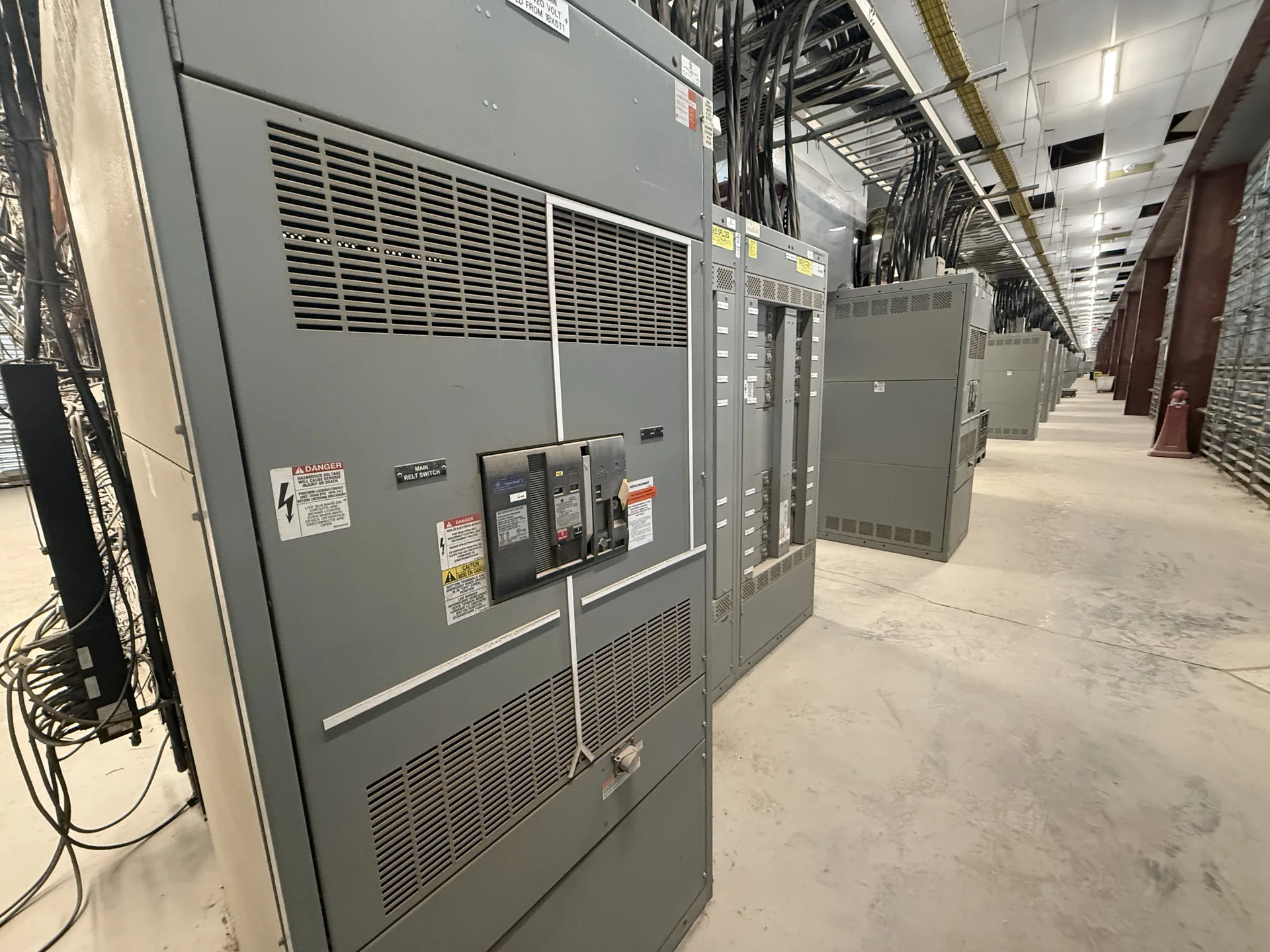
Scope a 800 A continuous-rating requirement around the relationship between bus and main-device ratings; verify actual bus, device, conductor, ambient, and short-circuit ratings for the selected assembly. Useful specifications connect the source, protective devices, feeders and physical installation rather than treating each in isolation. Our team builds and supplies new equipment in the USA for North Carolina projects. Provide the information available now, including the intended voltage, current, environment and delivery needs. The engineer of record and the manufacturer can then identify what remains to be clarified before a project-specific quotation.
800 Amp Switchgear and Switchboard Specifications — project planning
Available fault current is a property of the electrical system at a particular point; interrupting and short-circuit ratings describe equipment capability. Check each breaker or fuse's interrupting rating at the applied voltage against the fault current it may need to interrupt. Separately verify the assembly's short-circuit current or withstand rating and any associated time, device or installation conditions. Include contributions from utility sources, generators and motors as applicable to the study. Series-rated device combinations require documented compatibility and application in accordance with their conditions, not an assumption based on individual ampere ratings.
A switchboard can organize a main disconnect and feeder protective devices in a floor-mounted distribution assembly. Define the number and size of feeders, metering needs, cable entry direction and required working clearances before selecting a layout. Depending on the design, molded-case, insulated-case or other suitable protective devices may be considered. UL 891 addresses switchboards rated no more than 1,000 V; it is not a medium- or high-voltage switchgear standard. Request the proposed assembly's voltage, continuous current and short-circuit ratings, along with any listing evidence required for the project.
UL 891: Understanding Switchboard Requirements
UL 891 is a standard for dead-front switchboards rated 1,000 volts or less. It is not the standard used to establish requirements for switchgear rated above 1,000 volts; that equipment requires consideration of other applicable standards and ratings. For a switchboard project, the specified voltage, continuous current, short-circuit current rating, and intended service conditions must match the application. A UL 891 listing must not be assumed from the use of listed components or the mention of the standard. Verify any claimed listing for the actual assembly using its markings and certification documentation.
Panelboards distribute power to branch circuits and can serve lighting, receptacle or equipment loads when properly selected. A useful schedule identifies system voltage, phase, wire count, main or main-lug configuration, branch circuit quantities and protective device ratings. Review available fault current at the panel location, the assembly rating and the interrupting ratings of installed breakers. Neutral capacity deserves particular attention where load imbalance or harmonics are expected. Reserve space for identified future circuits, and coordinate enclosure mounting, conductor entry, circuit labeling and required access with the installation drawings.
Busbar Work: Conductors and Support
Busbars distribute power within an assembly and must be designed as part of the complete electrical system. Conductor material, cross section, temperature rise, spacing, insulation, and support arrangement all affect suitability for the intended duty. The design must also account for mechanical forces associated with the specified short-circuit rating. Bending, punching, and routing should follow the approved construction details rather than rules of thumb alone. Phase identification and clear section interfaces help installers connect a lineup correctly while preserving required clearances and access.
A busbar joint depends on compatible materials, prepared contact surfaces, specified hardware, and the correct installation method. Surface treatment and joint compounds, when required, should follow the assembly and component instructions rather than a generic recipe. Fasteners should be tightened to the specified torque using suitable tools, with access provided for inspection and maintenance. The same care applies to field-installed splice connections between shipping sections. Unapproved drilling, substitution, or rework can affect current carrying capacity, clearances, or short-circuit performance and should be reviewed before proceeding.
Prepare a Switchgear Inquiry
A complete inquiry helps the project team compare equipment on the same technical basis. Include a current one-line diagram, load schedule, system voltage and grounding, available fault current, desired protective devices and any coordination requirements. Add site dimensions, access restrictions, cable entry, enclosure exposure and utility requirements. Identify applicable codes and standards, required third-party listing or inspection, submittal drawings and requested test documentation. Reserve future capacity explicitly rather than assuming it is included. A qualified engineer should review the final design, protective settings and installation against the project's actual conditions.
Enclosure selection starts with the actual location and exposure, not simply an indoor or outdoor label. Specify ambient temperature, altitude, humidity, dust, corrosive agents, water exposure and any washdown or ventilation needs. NEMA Type 1 is generally intended for indoor use, while Type 3R is commonly selected for certain outdoor weather exposures; confirm that the chosen type meets the full site conditions. Account for heaters, drainage, cable entry, working clearances and maintenance access where applicable. An environmental enclosure rating alone does not establish an arc-resistant rating or a specific equipment certification.
Prepare a Switchgear Quote Request
A useful quote request begins with the latest one-line diagram, project location, system voltage, phase and wire configuration, and required continuous current. Include available fault current or the engineer's required short-circuit rating, the number and ratings of incoming and outgoing circuits, and whether the equipment serves as service entrance or downstream distribution. Share enclosure requirements, metering, communications, spare capacity, and preferred delivery dates. Attach specifications and identify open questions rather than guessing. A complete package helps the manufacturer identify assumptions, compare options, and return a quote suited to the new equipment your project needs.
The price of new distribution equipment depends on its electrical ratings, physical construction, and included components. Main and feeder device types, bus material and capacity, short-circuit requirements, enclosure rating, metering, controls, and spare provisions can all affect the proposal. Engineering, testing, special documentation, freight, and site services may be included or quoted separately. Provide comparable specifications to each supplier and review exclusions, alternates, and payment terms alongside the base price. If the design is incomplete, ask which assumptions are driving the estimate and what could change when the drawings are finalized.
Start with the right specifications
Final capabilities and ratings are confirmed against the application, approved drawings and quotation.
| Project detail | What to provide |
|---|---|
| System | Voltage, phase, wiring and grounding |
| Current | Main and feeder ratings; load information |
| Protection | Available fault current, SCCR and protective device requirements |
| Installation | Enclosure, space, utility requirements and destination |