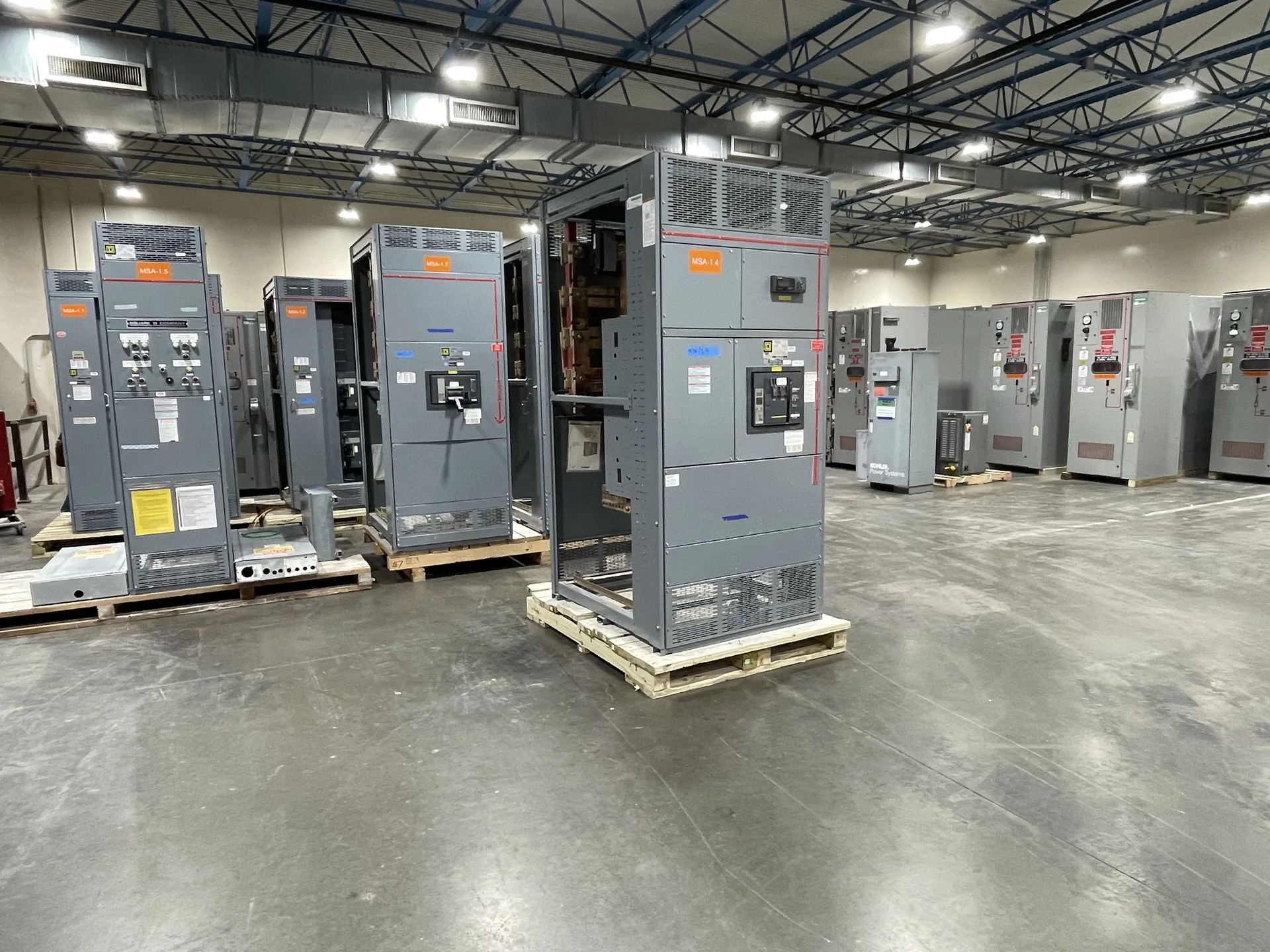
Review the 35 kV equipment class and confirm system voltage, insulation level, fault duty, installation, and the applicable equipment standard. The starting point is the actual electrical system and how the lineup will be installed and operated. We build and supply new power distribution equipment in the United States for North Carolina projects. Share the intended ratings, application, available space and schedule with our team so they can be evaluated against the proposed scope. The final configuration, availability and delivery details are established in the project quotation.
35 kV Switchgear Specifications — project planning
A short-circuit study estimates the fault current available at points throughout the electrical system. The engineer may need utility source data, transformer ratings and impedances, conductor lengths and sizes, motor contributions, and information about generators or other sources. Different operating configurations can produce different results. Provide the study or the project's specified fault-current requirements with the quote request so the proposed assembly and protective devices can be evaluated against the expected duty. Revisit the study when sources, equipment, or system arrangements change; a preliminary figure is not a substitute for the completed engineering review.
Installation planning starts with the approved equipment dimensions, shipping splits, weights, and manufacturer's handling instructions. Check the route from the unloading point to the electrical room, including doors, elevators, floor loading, rigging access, and the final equipment pad or supports. Coordinate conduit locations, cable bending space, grounding, utility interfaces, and any required shutdown with the responsible trades. Define who will store, assemble, install, test, and commission the equipment. Arrange inspections and any required permits before energization. Early coordination can reveal access or sequencing problems while there is still time to address them.
Shipment: Preparing Equipment for Installation
Shipment planning considers the size, weight, center of gravity, and handling needs of each equipment section. A lineup may be divided into shipping sections when required by transportation limits or the path into the building. Documentation should identify section order, loose components, splice materials, and any handling or storage instructions supplied with the equipment. Packaging and protection should reflect the expected transit and storage conditions without assuming the enclosure alone is adequate for outdoor storage. On arrival, the receiving team should inspect for damage and document discrepancies before installation.
A complete inquiry helps the project team compare equipment on the same technical basis. Include a current one-line diagram, load schedule, system voltage and grounding, available fault current, desired protective devices and any coordination requirements. Add site dimensions, access restrictions, cable entry, enclosure exposure and utility requirements. Identify applicable codes and standards, required third-party listing or inspection, submittal drawings and requested test documentation. Reserve future capacity explicitly rather than assuming it is included. A qualified engineer should review the final design, protective settings and installation against the project's actual conditions.
Inspection and Testing: Verifying Assembly Details
Inspection provides a structured way to compare an assembled lineup with its approved drawings and component instructions. A review can include device identification, conductor routing, barriers, grounding connections, hardware, labels, and the condition of the enclosure. Mechanical checks may cover door operation, interlocks, and the fit of removable sections where applicable. Findings should be documented and resolved before release. The inspection scope and acceptance criteria belong in the project documentation, because a visual check alone cannot establish every electrical rating or demonstrate performance under fault conditions.
Protection coordination considers how upstream and downstream devices respond to faults and overloads. The goal is often to isolate the affected circuit while keeping as much of the remaining system in service as practical. Where selective coordination is required, the engineer must evaluate the applicable devices across the required range of currents and operating times. Time-current curves, manufacturer coordination tables, available fault current, and actual trip settings may all matter. Share continuity requirements and relevant system information early; a high equipment rating or adjustable trip unit does not by itself prove selective coordination.
Modernization: Designing for Updated Requirements
Modernization can involve supplying a new switchgear or switchboard lineup for a project that needs updated distribution, monitoring, or control functions. The design may incorporate metering, protective relays, communications interfaces, or provisions for future circuits when specified. Each addition needs a defined purpose, power source, wiring interface, and compatibility review. Existing upstream and downstream equipment also influences fault protection and operating sequences. Before the design is finalized, the project team should confirm responsibility for system studies, integration, installation, and acceptance so that new equipment fits the overall plan.
Control and metering wiring connects devices such as relays, switches, indicators, and instrument transformers to the functions shown on the project drawings. Conductor size, insulation, terminal selection, and routing should reflect circuit ratings and the installation environment. Labels at both ends make circuits easier to trace during startup and future maintenance. Separation and mechanical support can reduce interference and protect wiring from sharp edges or moving parts. Particular care is needed with current transformer secondary circuits: their connections and test procedures must follow the equipment instructions and applicable safety practices.
Plan for Final Acceptance
Final acceptance involves more than receiving a shipment or approving a drawing. Establish the required factory documentation, delivery inspection, installation checks, field tests, and commissioning responsibilities in the contract. Compare nameplate information and the installed configuration with approved documents, and resolve outstanding punch-list items. The installing contractor and qualified testing personnel should complete the checks assigned to them before energization. Coordinate utility requirements and inspection by the authority having jurisdiction when applicable. Document the results and obtain the approvals required by the project; no single review automatically substitutes for all others.
Short-circuit current rating, or SCCR, describes the fault current an assembly or component can withstand under specified conditions at a stated voltage. A breaker's or fuse's interrupting rating describes the fault current that device can safely interrupt under specified conditions. Both must be considered against the available fault current at the installation point; a high breaker rating alone does not establish the assembly rating. A qualified designer should also review any conditions attached to the equipment rating. Series-rated combinations require specific permitted device combinations and application checks, not an assumption based on the upstream breaker alone.
Start with the right specifications
Final capabilities and ratings are confirmed against the application, approved drawings and quotation.
| Project detail | What to provide |
|---|---|
| System | Voltage, phase, wiring and grounding |
| Current | Main and feeder ratings; load information |
| Protection | Available fault current, SCCR and protective device requirements |
| Installation | Enclosure, space, utility requirements and destination |