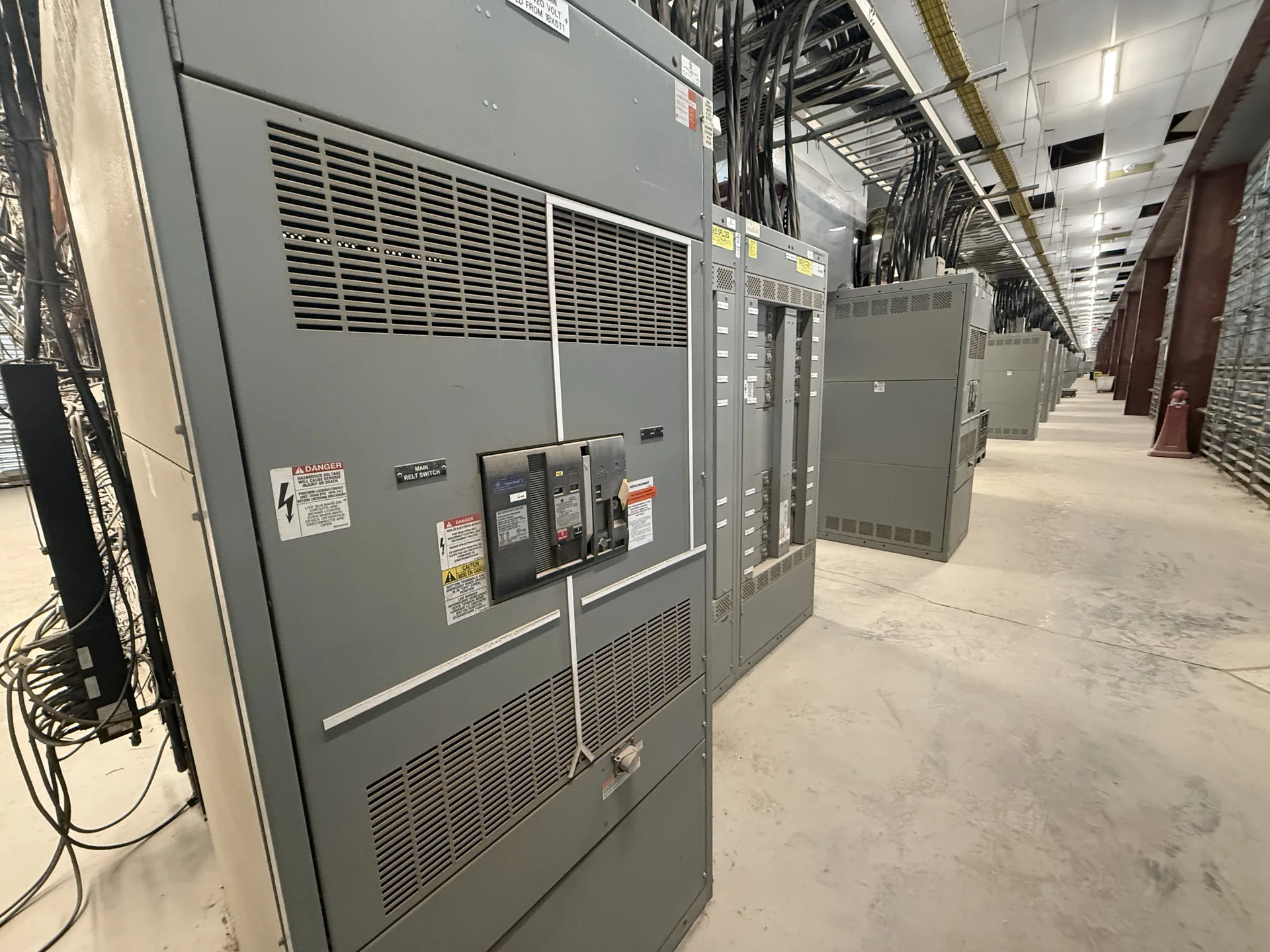
Assess three-phase service, 277 V line-to-neutral loads where available, grounding, feeder devices, and the actual utility arrangement. The equipment selection should follow the actual source characteristics, connected loads, operating requirements and installation environment. We manufacture new power distribution equipment in the United States and serve customers across North Carolina. Tell us what is known about the one-line, desired configuration and target delivery schedule. A project review establishes the proposed scope and identifies ratings or documentation that need confirmation.
277 480 Volt Switchgear Specifications — project planning
A 277/480 V three-phase wye system has 480 V between phases and 277 V from phase to neutral when that neutral is available. Similarly, 347/600 V describes a wye system with 600 V phase-to-phase and 347 V phase-to-neutral. A 480 V designation by itself does not establish a 277 V neutral: the source may use another configuration or the neutral may not be brought to the equipment. State the actual voltage, grounding and wire count, and confirm that each proposed device is suitable for its applied voltage and circuit configuration.
Neutral and grounding arrangements affect the equipment design as well as the installation. Identify the system configuration, neutral conductor needs, ground bus, service or feeder application, and any ground-fault protection requirements. The electrical engineer should specify where neutral-to-ground bonding is required and where the neutral must remain isolated, using the adopted code and the actual source configuration. Transformers and generator transfer arrangements can introduce separately derived system questions. Provide these details before drawings are approved, and do not assume that a bonding arrangement suitable at one location is appropriate everywhere downstream.
Phase Design and Load Balance
Phase design should begin with the source configuration and the voltage and phase requirements of the connected loads. Distinguish single-phase and three-phase loads, identify any neutral requirements, and provide the engineer with a realistic load schedule. Distribution planning should consider phase balance, nonlinear loads, conductor sizing, grounding, and the effect of motor starting on the system. Where multiple sources or transfer equipment are involved, document the neutral switching and grounding approach for coordinated review. Procurement drawings should communicate phase arrangement and termination requirements clearly to the installation team.
Service-entrance equipment connects the utility supply to a facility's distribution system and must be coordinated with the utility and the authority having jurisdiction. Establish the service voltage, available fault current, point of connection, metering arrangement, conductor entry and service disconnect configuration early. Specify whether the assembly must be suitable for use as service equipment and verify the proposed markings and documentation. Grounding and neutral bonding must follow the applicable code and the actual service arrangement. Include utility access, required clearances and any restrictions on customer-installed metering or protective devices.
Prepare a Switchgear Inquiry
A complete inquiry helps the project team compare equipment on the same technical basis. Include a current one-line diagram, load schedule, system voltage and grounding, available fault current, desired protective devices and any coordination requirements. Add site dimensions, access restrictions, cable entry, enclosure exposure and utility requirements. Identify applicable codes and standards, required third-party listing or inspection, submittal drawings and requested test documentation. Reserve future capacity explicitly rather than assuming it is included. A qualified engineer should review the final design, protective settings and installation against the project's actual conditions.
A useful quote request begins with the latest one-line diagram, project location, system voltage, phase and wire configuration, and required continuous current. Include available fault current or the engineer's required short-circuit rating, the number and ratings of incoming and outgoing circuits, and whether the equipment serves as service entrance or downstream distribution. Share enclosure requirements, metering, communications, spare capacity, and preferred delivery dates. Attach specifications and identify open questions rather than guessing. A complete package helps the manufacturer identify assumptions, compare options, and return a quote suited to the new equipment your project needs.
Commissioning: Functional Checks and Handover
A commissioning plan should define what is tested, who performs each step, and what evidence is needed for acceptance. Depending on the equipment and project, checks may include device operation, control sequences, metering signals, alarms, and communication with the facility system. Qualified personnel should use procedures appropriate to the equipment and coordinate any energization with the site owner and other responsible parties. Handover documents can include final drawings, test records, equipment instructions, and a list of unresolved items. Actual testing and services depend on the agreed project scope.
The price of new distribution equipment depends on its electrical ratings, physical construction, and included components. Main and feeder device types, bus material and capacity, short-circuit requirements, enclosure rating, metering, controls, and spare provisions can all affect the proposal. Engineering, testing, special documentation, freight, and site services may be included or quoted separately. Provide comparable specifications to each supplier and review exclusions, alternates, and payment terms alongside the base price. If the design is incomplete, ask which assumptions are driving the estimate and what could change when the drawings are finalized.
Enclosure and Site Selection
Enclosure selection starts with the actual location and exposure, not simply an indoor or outdoor label. Specify ambient temperature, altitude, humidity, dust, corrosive agents, water exposure and any washdown or ventilation needs. NEMA Type 1 is generally intended for indoor use, while Type 3R is commonly selected for certain outdoor weather exposures; confirm that the chosen type meets the full site conditions. Account for heaters, drainage, cable entry, working clearances and maintenance access where applicable. An environmental enclosure rating alone does not establish an arc-resistant rating or a specific equipment certification.
A project-specific equipment layout connects electrical requirements to the space available for installation and maintenance. Section dimensions, cable entry, conductor bending space, ventilation, and access to operating devices all influence the arrangement. The design should account for doors, removable covers, lifting provisions, and the working clearances required at the installed location. Coordination with the building team helps identify obstructions, floor loading, and the route into the electrical room. A documented layout also makes it easier to review future expansion without assuming unused space is automatically suitable for additional equipment.
Start with the right specifications
Final capabilities and ratings are confirmed against the application, approved drawings and quotation.
| Project detail | What to provide |
|---|---|
| System | Voltage, phase, wiring and grounding |
| Current | Main and feeder ratings; load information |
| Protection | Available fault current, SCCR and protective device requirements |
| Installation | Enclosure, space, utility requirements and destination |