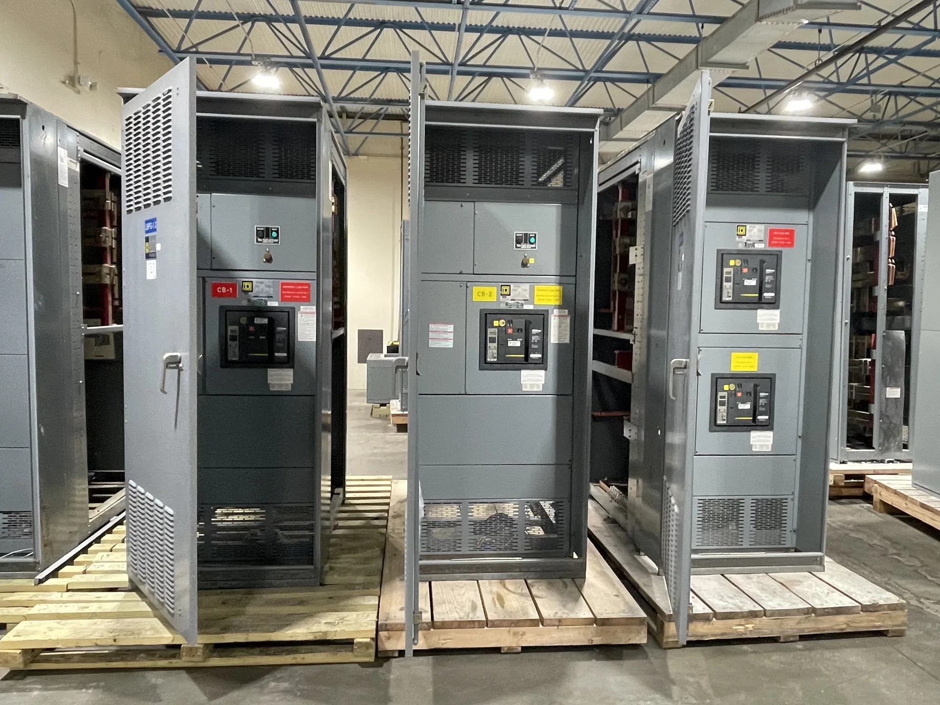
Review the 15 kV equipment class, maximum system voltage, insulation levels, fault duty, cable terminations, and utility interfaces. Useful specifications connect the source, protective devices, feeders and physical installation rather than treating each in isolation. Our team builds and supplies new equipment in the USA for North Carolina projects. Provide the information available now, including the intended voltage, current, environment and delivery needs. The engineer of record and the manufacturer can then identify what remains to be clarified before a project-specific quotation.
15 kV Switchgear Specifications — project planning
Utility-facing switchgear projects require early coordination over the boundary between the utility system and customer-owned distribution. The procurement package should identify the point of connection, incoming source characteristics, metering arrangements, protection responsibilities, and the information needed for the utility's review. Show current and voltage transformer locations where applicable, along with communication and control interfaces. Confirm assumptions about available fault current and future system changes with the responsible parties. Clear ownership and operating responsibilities help avoid gaps when equipment is commissioned, switched, or maintained.
Commissioning brings the equipment and the wider installation together through a planned sequence of checks before service. The project team should confirm anchorage, accessible clearances, cable terminations, grounding, section splices, and control connections against the drawings and installation instructions. Utility interfaces, protective device settings, and remote signals may require coordination with other parties. Responsibilities for tests, documentation, and energization should be established in advance. Work on electrical equipment must follow applicable safety requirements, including deenergization, lockout or tagging, and verification of the deenergized condition where required.
Use a Fault Study to Set Ratings
A short-circuit study estimates the fault current available at points throughout the electrical system. The engineer may need utility source data, transformer ratings and impedances, conductor lengths and sizes, motor contributions, and information about generators or other sources. Different operating configurations can produce different results. Provide the study or the project's specified fault-current requirements with the quote request so the proposed assembly and protective devices can be evaluated against the expected duty. Revisit the study when sources, equipment, or system arrangements change; a preliminary figure is not a substitute for the completed engineering review.
A lead-time estimate is more useful when its starting point and milestones are clear. Ask whether the estimate begins at order acceptance, receipt of required commercial information, approval of drawings, or release for production. Break the schedule into engineering, customer review, component procurement, assembly, inspection, and freight. Breakers, metering, special enclosures, and design changes can affect the schedule, as can delayed approvals. Share the required on-site date and any outage or construction constraints. Request an updated schedule when assumptions change, and distinguish an estimate from a confirmed commitment.
Maintenance Access and Safe Isolation
Switchgear layouts should give qualified personnel a practical way to inspect, test, isolate, and maintain equipment over its service life. Show required working space, door swing, cable access, and the route for removing major components on the project drawings. Identify isolation points and any alternate feeds or control-power sources that could leave parts energized. Procurement specifications can request durable labeling, accessible test provisions, and documentation of operating sequences. Maintenance plans should use site-specific procedures for controlling hazardous energy and verifying absence of voltage before work begins.
Busbars distribute power within an assembly and must be designed as part of the complete electrical system. Conductor material, cross section, temperature rise, spacing, insulation, and support arrangement all affect suitability for the intended duty. The design must also account for mechanical forces associated with the specified short-circuit rating. Bending, punching, and routing should follow the approved construction details rather than rules of thumb alone. Phase identification and clear section interfaces help installers connect a lineup correctly while preserving required clearances and access.
Enclosure and Site Selection
Enclosure selection starts with the actual location and exposure, not simply an indoor or outdoor label. Specify ambient temperature, altitude, humidity, dust, corrosive agents, water exposure and any washdown or ventilation needs. NEMA Type 1 is generally intended for indoor use, while Type 3R is commonly selected for certain outdoor weather exposures; confirm that the chosen type meets the full site conditions. Account for heaters, drainage, cable entry, working clearances and maintenance access where applicable. An environmental enclosure rating alone does not establish an arc-resistant rating or a specific equipment certification.
Modernization can involve supplying a new switchgear or switchboard lineup for a project that needs updated distribution, monitoring, or control functions. The design may incorporate metering, protective relays, communications interfaces, or provisions for future circuits when specified. Each addition needs a defined purpose, power source, wiring interface, and compatibility review. Existing upstream and downstream equipment also influences fault protection and operating sequences. Before the design is finalized, the project team should confirm responsibility for system studies, integration, installation, and acceptance so that new equipment fits the overall plan.
Find the Right Supplier
Start with suppliers that offer the type of new equipment and voltage class specified for your project. Give each candidate the same one-line, specifications, delivery location, and schedule so their proposals can be compared fairly. Ask about design support, the proposed assembly's ratings and certification, component sourcing, documentation, and warranty process. Request confirmation of the sales channel and the person responsible for changes after order placement. Evaluate technical fit and responsiveness as well as price; a proposal that clearly identifies assumptions and exclusions is easier for your project team to review.
For projects across the United States, discuss freight requirements before accepting a delivery estimate. Provide the destination, site access restrictions, required delivery window, and whether a loading dock, forklift, or rigging crew is available. Ask how the assembly will be divided and packaged, who arranges unloading, and which freight and insurance terms apply. Confirm any special handling, storage, or weather protection needs with the supplier. On arrival, check the shipment against the packing list and document visible damage on the carrier's paperwork. Report suspected concealed damage promptly under the applicable claim procedures.
Start with the right specifications
Final capabilities and ratings are confirmed against the application, approved drawings and quotation.
| Project detail | What to provide |
|---|---|
| System | Voltage, phase, wiring and grounding |
| Current | Main and feeder ratings; load information |
| Protection | Available fault current, SCCR and protective device requirements |
| Installation | Enclosure, space, utility requirements and destination |